12
Manufactured by: Ronstan Denmark ApS. - Jægervænget 36 - 7100 Vejle – Denmark - info@andersenwinches - www.andersenwinches.com
Circuit breaker safety switch installation
The Compact motor is supplied with a special circuit breaker safety switch for the Compact motor
installation. The circuit breaker safety switch is fitted with a PCB (Print Circuit Board), which shall
be connected as described below. The system is a combined safety switch and PCB makes a reliable
circuit protection for the motor installation.
The safety switch system monitor: system conditions and cuts off the power if any error occurs.
Notice that the circuit breaker shall be placed very near the battery – see wiring diagram.
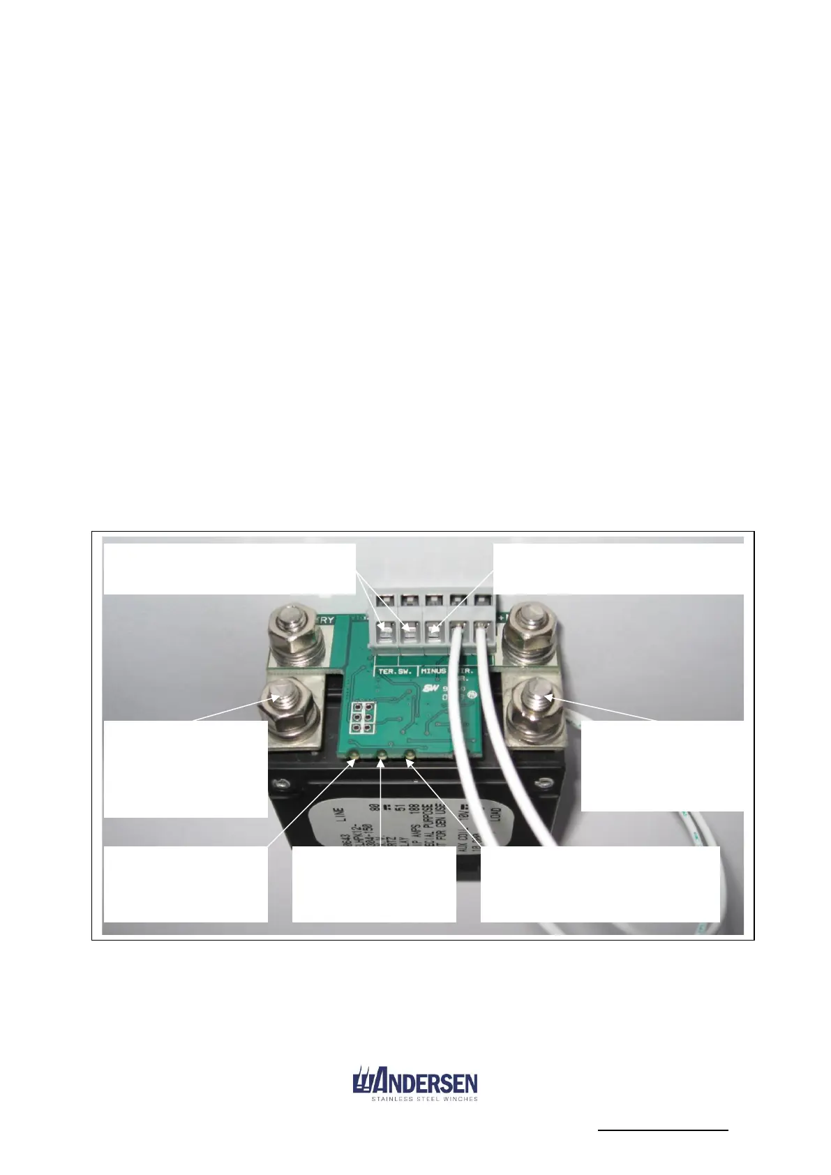
Circuit breaker installation
To install the switch, extend and
connect the 2 yellow wires from the
motor to the “TER. SW” connectors
on the back of the circuit breaker.
Connect the negative battery terminal
to the “MINUS” connector on the
back of the circuit breaker (0.75mm²
wire).
When installed correctly the green
diode light will turn on and off when
the circuit breaker is on and off.
Notice: when turning off the switch
the green diode will turn off with a
little delay of a few seconds.
o If the green light remains on when in
the “OFF” position the terminals to
the battery and winch need to be
swapped.
o If no light is present check the con-
nection to the “MINUS” terminal
o If all light is flashing the PCB
connection is wrong and the
“MINUS” terminal is missing
o Make sure all wires are connected
correct
Terminal to battery+
power (tighten the
terminal bolts with
5Nm torque).
Terminal to motor+
power (tighten the
terminal bolts with
5Nm torque)
Connect the extended cables from
the yellow wires on the motor
here.
Yellow diode light.
Flash the error type
when an error occurs
Connect minus from the battery
here.
Notice: You can TYPICAL add maximum a 50mm² tubular cable lugs on the circuit breaker -
this is regarding the free space around the print circuit board.
Be sure that cable lug, washers etc, doesn’t touch the print circuit board when installed.
Red diode light.
Lights when an
serious error occurs
Green diode light.
Lights when the circuit breaker
is “ON”, and no errors present