English - 57 -
6. SPDIF Digital Out outputs digital audio signals of the currently watched source.
Use a digital optic cable to transfer audio signals to a device that has SPDIF input.
7. RF Input/SAT. input connects to an aerial,cable and satellite antenna system.
Note that if you use a decoder or a media recorder, you should connect the aerial cable through the
device to the television with an appropriate antenna cable, as shown in the illustration in the following
pages.
8. HDMI 3: HDMI Input
9. HDMI 2: HDMI Input
10. HDMI 1: HDMI Input
HDMI Inputs are for connecting a device that has an HDMI socket. Your LED TV is capable of
displaying High Denition pictures from devices such as a High Denition Satellite Receiver or DVD
Player. These devices must be connected via the HDMI sockets or Component Socket. These sockets
can accept either 720p or 1080p (optional) signals. No sound connection is needed for an HDMI to
HDMI connection.
11. PC Input is for connecting a personal computer to the TV set.
Connect the PC cable between the PC INPUT on the TV and the PC output on your PC.
12. Ethernet input (for service and Internet connectivity)
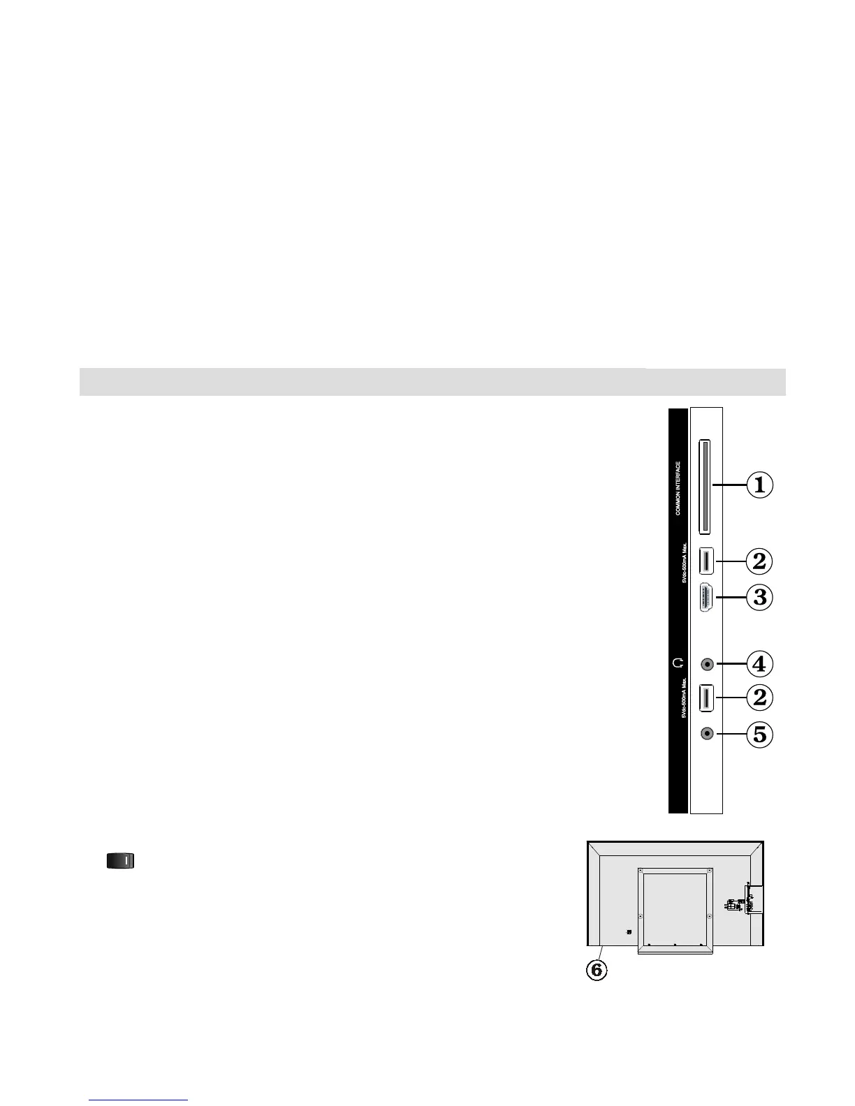
Viewing the Connections - Side Connectors
1. CI Slot is used for inserting a CI card. A CI card allows you to view all the
channels that you subscribe to. For more information, see “Conditional Access”
section.
2. Side USBs
Note that programme recording feature is available via these USB inputs. You can connect
external hard disk drives to this input.
3. Side HDMI Input is for connecting a device that has an HDMI socket.
4. Headphone jack is used for connecting an external headphone to the system.
Connect to the HEADPHONE jack to listen to the TV from headphones (optional).
5. Side audio-video connection input is used for connecting video and audio
signals of external devices. To make a video connection, you must use the
supplied AV connection cable for enabling connection. First, plug singular jack of
the cable to the TV’s Side AV socket. Afterwards, insert your video cable’s (not
supplied) connector into the YELLOW input (located on the plural side) of the
supplied AV connection cable. Colours of the connected jacks should match.
To enable audio connection, you must use RED and WHITE inputs of the side AV
connection cable. Afterwards, insert your device’s audio cable’s connectors into
the RED and WHITE jack of the supplied side AV connection cable. Colours of
the connected jacks should match.
Note: You should use audio inputs of side AV connection cable (RED & WHITE)
to enable sound connection when connecting a device to your TV by using PC or
COMPONENT VIDEO input.
6. , switch is used for turning the TV on or off.
USB 1
S-AV
HDMIUSB 2