MAXXo Water Heater
1717
INSTALLATION • SECTION 3
master
230V/50Hz
br wh
br
br
br
wh
wh
gr
gr
gr
gr
r
r
r
r
wh
comm. 2
comm. 3
comm. 4
comm. 1
y
gy
r
br
bl
br bl
r r
bl
wh
bk
bl
br
bl
y
or
y
br
gy
br
bl
br gy
br
bl
gy
bk
y
AL1
AL2
TS1
TS2
TS3
TS4
br
bl
br
bl
br
br
br
bl
bl
bl
br
br
br
bl
bl
bl
gy
gn
bk
or
y
r
y
bk
r
bk
gr
or
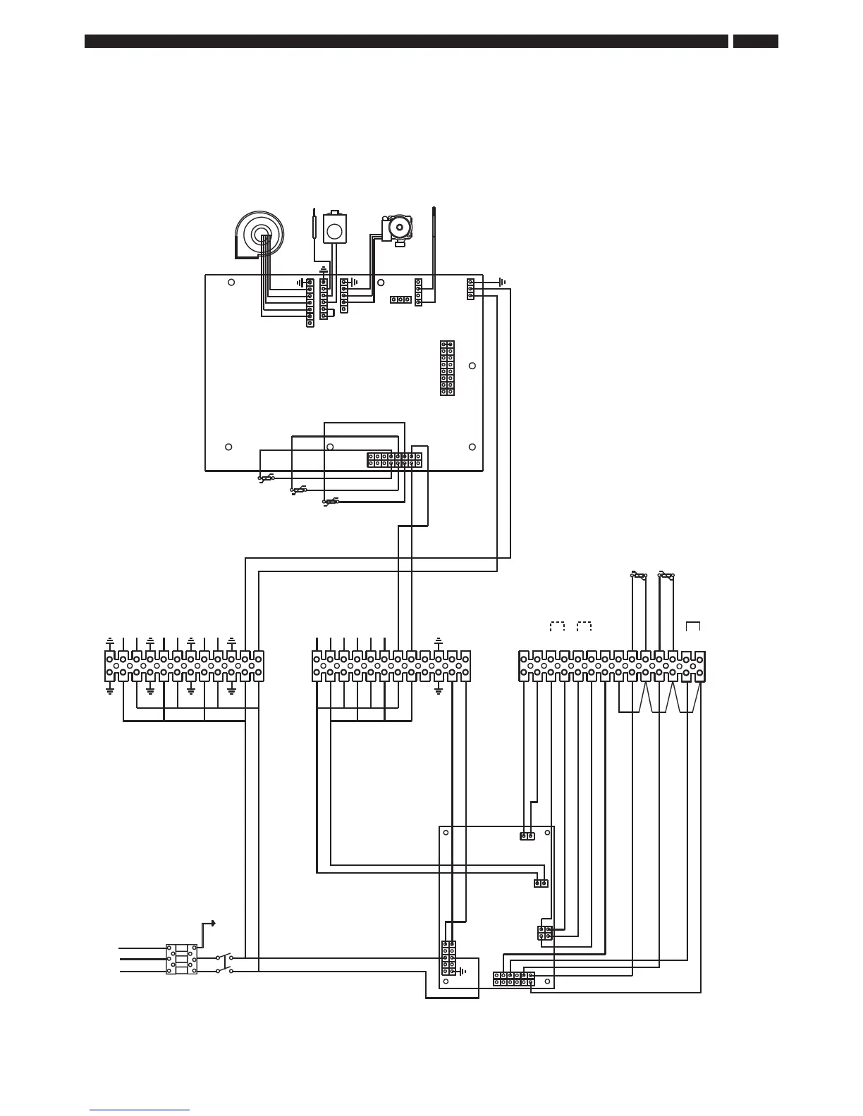
AL1-AL2 = Alarm
BT1-BT2 = Activate Second Setpoint
TH1-TH2 = Activate Secondary Pump
LS1-LS2 = Secondary Sensor
TS1-TS2 = Tank sensor, low position
EN1-EN2 = enable / disable
bl = blue
br = brown
y = yellow
gn = green
gy = grey
or = orange
br
bl
BT1
BT2
LS1
LS2
TH1
TH2
L N
br
bl
br bl
br
r = red
wh = white
bk = black
pi = pink
bl
bk
pi
or
flow sensor 2
flow sensor 1
return sensor
slave 1
fan
ionisation rod
gasvalve
primary
pump
glow plug
tank sensor, low position
mains 1
mains 2
mains 3
mains 4
pump
pump L
secondary
pump
pump N
M5879D
wh
(Max 24 V 1.0 Amp)
E
g/y
g/y = green & yellow
EN1
EN2
tank sensor, high position
TS3-TS4 = Tank sensor, high position
r/bl
bk
gy
r/bl
r
bk
}
gn
Fig. 7 – Wiring Diagram
Make sure that the phase (L) and the neutral (N) are connected to the correct terminals on the connector. e appliance is
phase sensitive therefore swapping the phase and neutral will lead to a fault in the appliance.