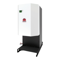
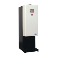
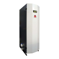
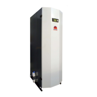
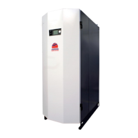
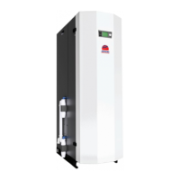
MAXXo Water Heater
3232
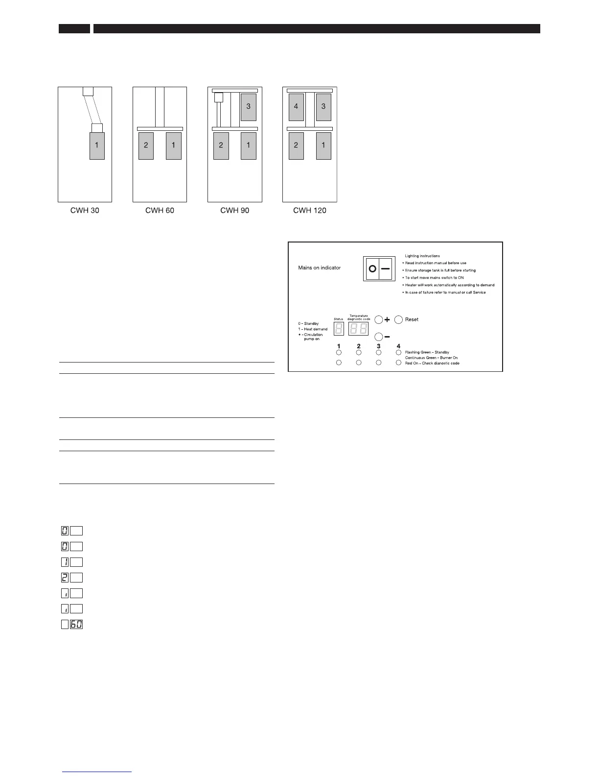
CWH HEAT EXCHANGER CONFIGURATION
CONTROL PANEL
e operational status of the water heater can be seen
and the desired temperature can be set on the control
panel
(Fig 13, right)
A green and a red LED can be found on the control panel
for each burner module. ese indicate the status of the
corresponding burner module.
e green LED:
– off no automatic burner detected
– ashing automatic burner detected, burner module
not in use
– on burner module in use
e red LED:
– off no fault
– ashing blocking fault
– on locking fault
e display on the control panel consists of 3 segments.
e following codes can appear:
No heat demand
Flashing, water not enabled
Heat demand
Programme changed, water temperature activated
Permanent, circulation pump connected to terminals pump L – pump N activated
Flashing, circulation pump stand by
Actual water heater temperature
Fig 13
e water heater is equipped with 1,
2, 3 or 4 burner modules depending
on the model. Each burner module
has its own automatic burner.
SECTION 3 • INSTALLATION