Modular Power Meter
Modular power meter version 1.0 Page 39 / 40
List of figures
Figure 5-1 Block schematic of a current input, only one channel is shown ........................ 8
Figure 5-2 Volt sensor act as bridge from MODBUS to sensor bus .................................... 9
Figure 5-3 RoCo2000AN sensor act as bridge from MODBUS to sensor bus ....................... 9
Figure 5-4 Sensors can be mixed, but Volt must be first and Spark must be the last ......... 9
Figure 5-5 Volt or RoCo can be used as a single device ................................................... 9
Figure 5-7 Volt1000, Cube1000AN & RoCo2000AN chain Configuration .......................... 10
Figure 5-6 MODBUS RTU cable pinning ........................................................................ 10
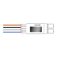
Figure 5-9 Volt1000 Module ......................................................................................... 11
Figure 5-10 Current module with Rogowski coils ........................................................... 12
Figure 11 Cube 1000AN current sensor ........................................................................ 12