Modular Power Meter
Modular power meter version 1.0 Page 8 / 40
5. Instrument Description
The modular power meter consists of voltage (Volt1000) and current
(Cube1000AN/RoCo2000AN) meters with a modbus interface. The Spark5A can be added and
has 5A (20Apeek) range with an ultrasonic microphone to detect partial discharges.
This meter is intended to be used together with a MODBUS RTU master (often a PLC). To
avoid a lot of cabling, the different meters can be connected in a chain to become a
cascaded multi-channel meter. Only one cable should be connected to the RTU master to
measure up to 15 x 4 = 60 power lines.
This modular system consist of a voltage module (Volt1000) that measures L1,L2,L3,N, and
one up to fifteen current modules (Cube1000AN/RoCo2000AN) measure power and current.
In other words, for up to 15 3-phase+N outgoing power lines, it is possible to measure the
voltage, current and power for the 3 phases and the voltage & current in the Neutral.
To accomplish this, the Volt1000 meter samples the voltage and sends the samples to the
Cube1000AN/RoCo2000AN meters on the cascade bus. Each Cube1000AN/RoCo2000AN
meter uses these samples to calculate the power components.
The Volt1000 meter acts as a bridge between the MODBUS master and the cascade bus.
If it is not necessary to measure the voltage, also the first Cube1000AN/RoCo2000AN can
form the bridge between MODBUS and the other current sensors.
The meter uses a dual meter principle.
When buying a multi-meter, one has to choose between a manual- or an auto ranging one.
The disadvantage of an auto ranging meter is that, during the range switch, no
measurements are available. The disadvantage of a manual selection is that we lose all
measurements if an erroneous range is selected.
Our solution is the combination of both. Each voltage or current input goes to a fix range
input and to an auto ranging input. The fix range input is set to the maximum range while
the auto ranging one follows the input. Software selects the right measurement.
With this double meter principle, we get a maximum resolution by auto ranging, while peaks
are always catched by the fixed range.
A second benefit is that we get a high crest factor, because the maximum range is always
available.
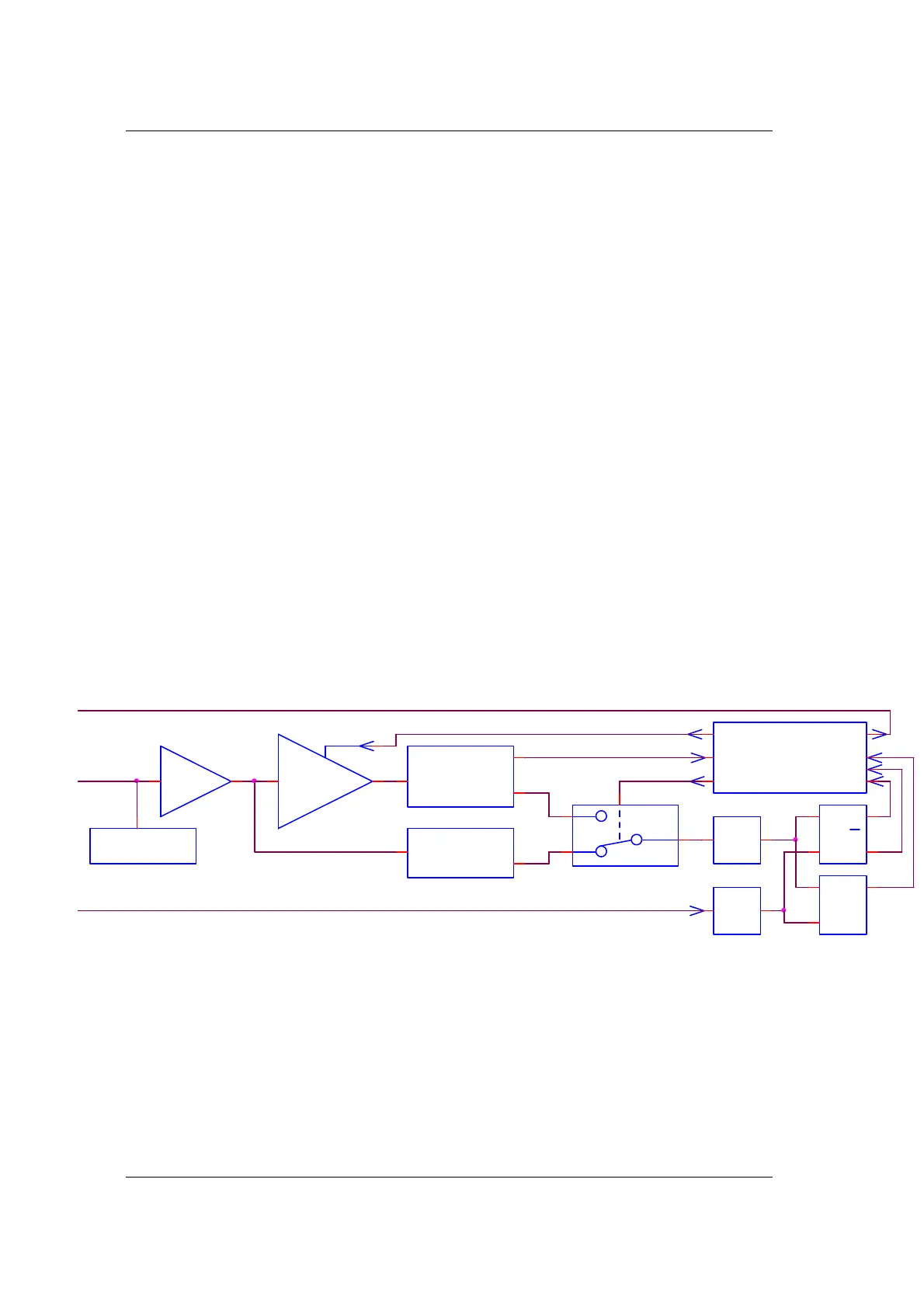
Each input has his own analog to digital convertor, to get a full-bandwidth measurement with
a maximum resolution.
PreAmp
Protection
Select
FFT
FFT
ADC_1
Overrange
Samples
ADC_5
Samples
PGA_1
Range
x3
x7
x15
x31
x61
Fix range
Samples f rom Volt1000
Current
U*I
U
PI
Q
UxI
U
SI
uP
Select
OV
Range Output
P
Q
S
Results sent to Volt1000
Figure 5-1 Block schematic of a current input, only one channel is shown