Modular Power Meter
Modular power meter version 1.0 Page 9 / 40
5.1.
Configurations.
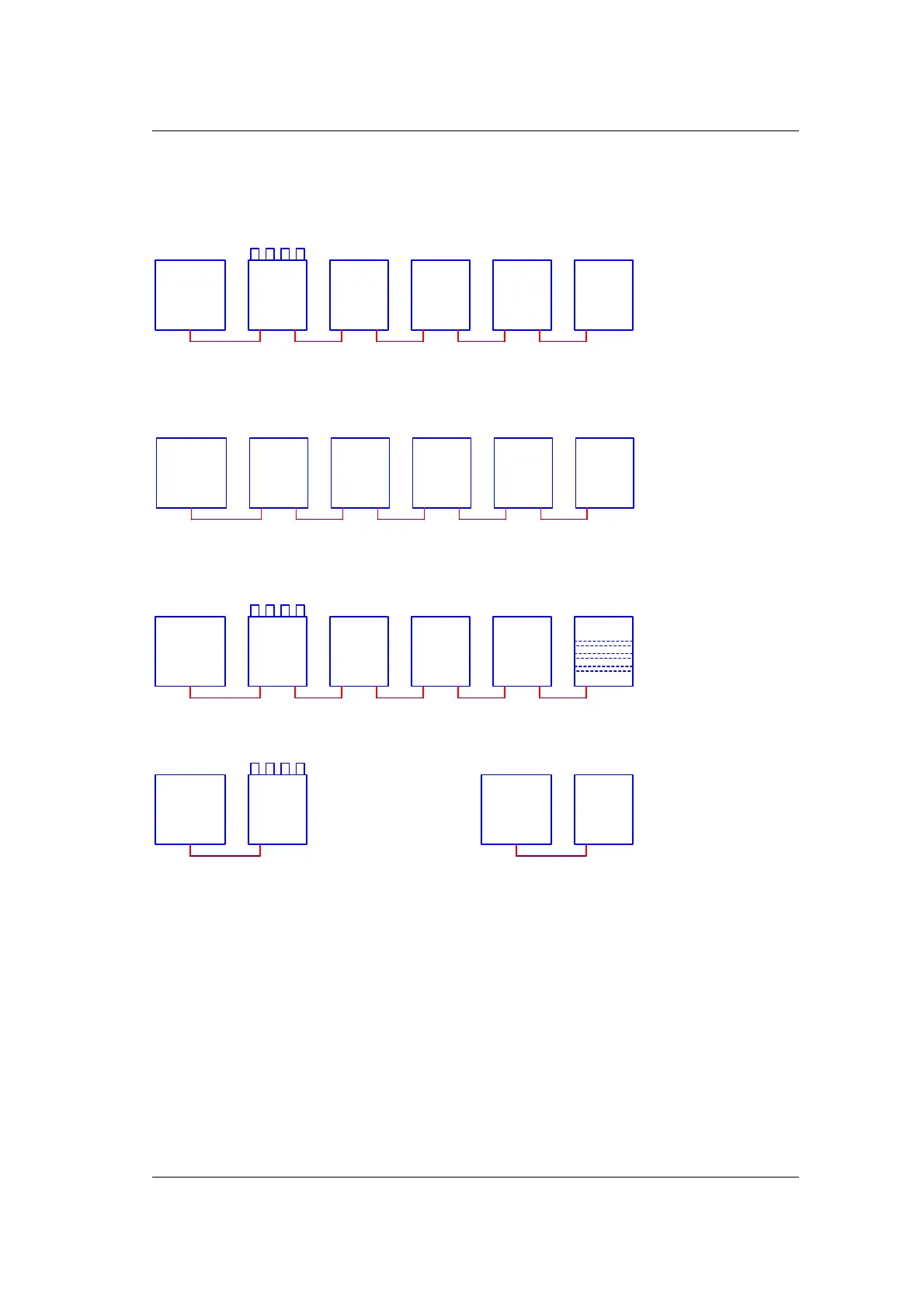
Different configurations are possible, hereunder we show some as an indication.
In all configurations, the first module acts for MODBUS as bridge to the other sensors. The
modbus address equals the MODBUS address of the first sensor plus the position of the
sensor in the cascade. I.e.: if the first sensor has the address 10, then the next will have 11,
and so on. To make it easier for you, we call the first module sensor_0 the next module
sensor_1, etc. so the number is the offset of the MODBUS address.
Master
(PLC)
RTU
MODBUS
Volt-
1000
RTU
BUS
SENSOR_0
RoCo-
2000AN
BUSBUS
SENSOR_1
RoCo-
2000AN
BUSBUS
SENSOR_2
RoCo-
2000AN
BUSBUS
SENSOR_3
RoCo-
2000AN
BUS NC
SENSOR_4
Figure 5-2 Volt sensor act as bridge from MODBUS to sensor bus
Master
(PLC)
RTU
MODBUS
RoCo-
2000AN
BUSBUS
SENSOR_1
RoCo-
2000AN
BUSBUS
SENSOR_2
RoCo-
2000AN
BUS NC
SENSOR_4
RoCo-
2000AN
BUSRTU
SENSOR_0
Cube-
1000AN
SENSOR_3
Figure 5-3 RoCo2000AN sensor act as bridge from MODBUS to sensor bus
Figure 5-4 Sensors can be mixed, but Volt must be first and Spark must be the last
Master
(PLC)
RTU
MODBUS
Cube-
1000AN
SENSOR_1
Cube-
1000AN
SENSOR_2
Cube-
1000AN
SENSOR_3
Spark
BUS NC
SENSOR_4
Volt-
1000
RTU
BUS
SENSOR_0
Master
(PLC)
RTU
MODBUS
RoCo-
2000AN
RTU NC
SENSOR_0
Master
(PLC)
RTU
MODBUS
Volt-
1000
RTU
NC
SENSOR_0
Figure 5-5 Volt or RoCo can be used as a single device