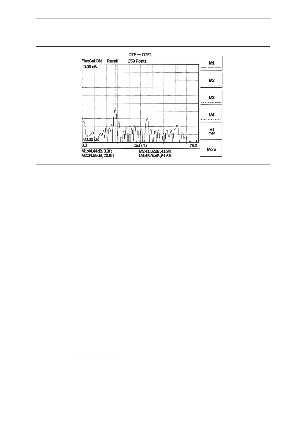
Figure 4-4 shows an example of a typical DTF return loss measurement trace using a
FlexCal calibration.
In the above example:
q
Marker M1 marks the first connector, the end of the Site Master phase stable Test
Port Extension cable.
q
Marker M2 marks the first jumper cable.
q
Marker M3 marks the end of the main feeder cable.
q
Marker M4 is the load at the end of the entire transmission line.
Procedure - DTF-SWR Mode
The following steps explain how to measure DTF in SWR mode.
Step 1. Press the
MODE key.
Step 2.
Select the
DTF-SWR using the Up/Down arrow key and press ENTER.
Step 3. Follow the same procedure as DTF-Return Loss mode, above.
Resolution
There are three sets of data points (130, 259 and 517) available in the Site Master. The fac-
tory default is 259 data points. By increasing the number of data points the measurement
accuracy and transmission line distance to measure will increase.
Step size =
(. )( )15 10
8
× Vp
FΔ
Where V
p
is the relative propagation velocity of the cable and DF is the stop frequency mi-
nus the start frequency (Hz).
The maximum distance is: D
max
= step size ´ (# of datapoints – 1)
4-8
Chapter 4 Cable & Antenna Measurements
Figure 4-4. Typical DTF Return Loss Trace