10
4. PRINCIPLES OF MAGNETIC DRIVE PUMPS
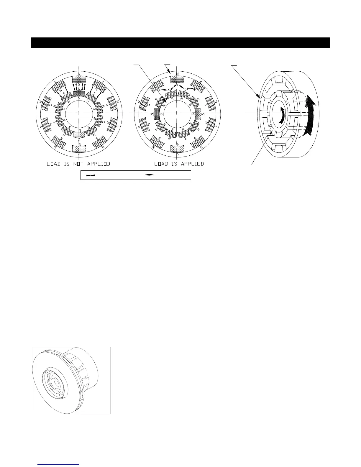
INNER YOKE
OUTER YOKE
OUTER MAGNET ASSEMBLY
INNER MAGNET ASSEMBLY
ATTRACTION REPULSION
Fig. 4-1
A magnetic coupling consists of two magnet assemblies. One is the outer assembly (the driver magnet)
and the other is the inner assembly (the driven magnet). The outer assembly is connected to a motor and
the inner assembly is indirectly or directly attached to a pump impeller. As Figure 4-1 shows, at rest,
magnet components of the outer assembly are aligned with their counterparts in the inner assembly.
When load (torque) is applied, the coupling deflects angularly and the magnets create a force of
simultaneous attraction and repulsion. This force is used to transfer torque from the motor to the
impeller.
This permanent-permanent magnet coupling creates neither slippage nor induction currents during
rotation. If excessive torque is applied, the magnets will de-couple. The magnets will not re-couple
unless the pump is stopped. There is no energy loss in this permanent-permanent coupling unless an
electrically conductive containment is placed between the outer and inner magnets. If an electrically
conductive material is used for the containment, eddy-currents will be generated which will cause some
energy loss. Ansimag's K+ Series pumps use only non-conductive containment shells. Ansimag's
K+ Series pumps have an inner magnet assembly which is indirectly attached to the impeller
(CFR/ETFE) or directly molded into the impeller (GFR/PFA ). The magnets are shown in Figure 4-2
behind the impeller.
Fi
. 4-2