61
ADDENDUM 1 - VERSA-TOOL FOR SHAFT SUPPORT
VERSA-TOOL INSTRUCTION MANUAL
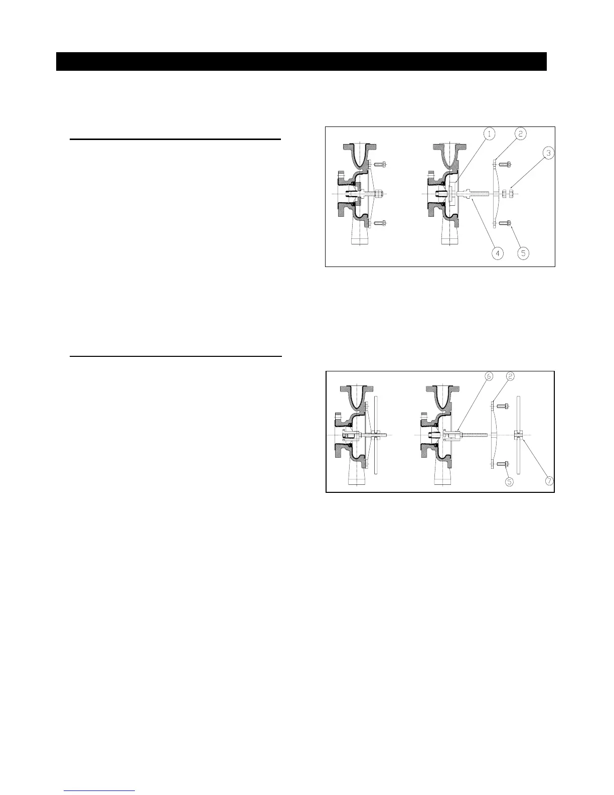
1. ASSEMBLING THE SHAFT SUPPORT
Insert the threaded shaft of Item 4 into the center
hole of Item 2. Turning clockwise, screw Item 4
onto Item 2 until it protrudes approximately 1”
from the other side of Item 2. Screw on the 5/8”
acorn nut (1 pc.) onto Item 4. Select the shaft
support adapter which corresponds to the shaft
support to be installed. Push Item 1 onto the
unthreaded end of Item 4. Insert the shaft support
thrust ring side first onto Item 4 until it rests against
Item 1. Bolt the Versa-tool into the casing. To
press in the shaft support, turn the acorn nut (Item
3) clockwise. Continue to turn until the shaft
support is resting against the shoulder in the casing.
Fig. A2-1
2. EXTRACTING THE SHAFT SUPPORT
Slide Item 6 into the shaft support. Turn clockwise
and pull back to engage the claws against the
spokes on the shaft support. Warning: To prevent
damage to the shaft support, make sure Item 6 is
fully engaged with the spokes on the shaft
support. Item 2 is designed to be used on 6” and
8” K Series and KM casings. Determine the type of
casing and assemble Item 2 onto the threaded shaft
of Item 6 until it rests flush against the back of the
pump casing. (Note: these parts do not thread
together as in Section 1, but should slide freely.)
Align the bolt holes on Item 2 with any threaded
holes in the casing and secure using Item 5 (2
pieces). Screw Item 7 onto Item 6
Fig. A2-2
clockwise until it rests against Item 2. To extract the shaft support, continue turning Item 7. Item 6 will
begin to pull forward, removing the shaft support with it. Continue turning until the shaft support is
fully out from the casing.