26
8-c. WET-END ASSEMBLY
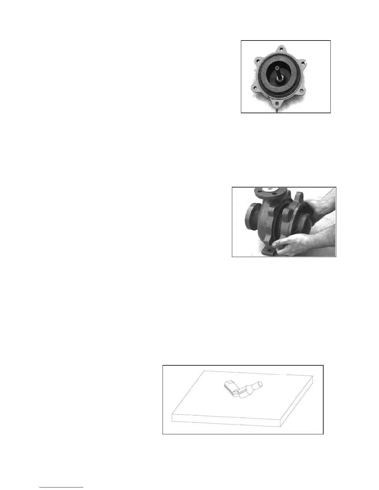
1. Insert the containment shell into the rear support. It is
necessary to properly align the containment shell such that the
groove in the shaft is “clocked” at the 11:00 O’clock position,
when viewed from the front. (On 8” models there is an arrow
cast onto the backside of the rear support, to indicate the “Up”
or 12:00 O’clock position. On 6” models, the rear support is
clocked with the two “grooved” ears horizontal. Either of the
points perpendicular to the horizontal may be chosen as the
top.) If necessary tap the containment shell into place with a
soft hammer until it is evenly seated.
Figure 8-8: Shaft and
Containment Shell in
Rear Support
2. Place the impeller assembly onto the shaft. (Make sure that the main bushing and mouth ring are
already installed in the impeller.)
3. Place the casing O-ring into the groove of the containment
shell.
4. While holding the O-ring in place, line up the end of the
shaft with the bore of the shaft- support in the pump casing
and fit the two casings together.
Caution!: Ensure that the rear support is properly
clocked so the shaft groove is at the 11:00 O’clock
position.
Fig. 8-9: Fit Casings Together
6. ANSI PUMPS are assembled using six 1/2"-13 x 1-3/4" hex bolts with a ¾” wrench. Bolt the rear
support onto the pump casing. Tighten the bolts to just snug at this time.
7. ISO PUMPS are assembled using six M12-1.75 x 45mm hex bolts. Bolt the rear support onto the
pump casing. Tighten the bolts to just snug at this time.
8. Confirm that the impeller has some axial endplay inside the casing of about 1/16" to 1/8" [1.6mm
to 3.2mm] by rocking the assembled wet end back and forth. You should hear the impeller moving
inside.
Caution: If pump shaft is
dropped on a hard surface such
as concrete, the impact may cause shaft
to break..
Fig. 8-10