27
9. DRIVE END ASSEMBLY (ANSI Pumps with NEMA Motors)
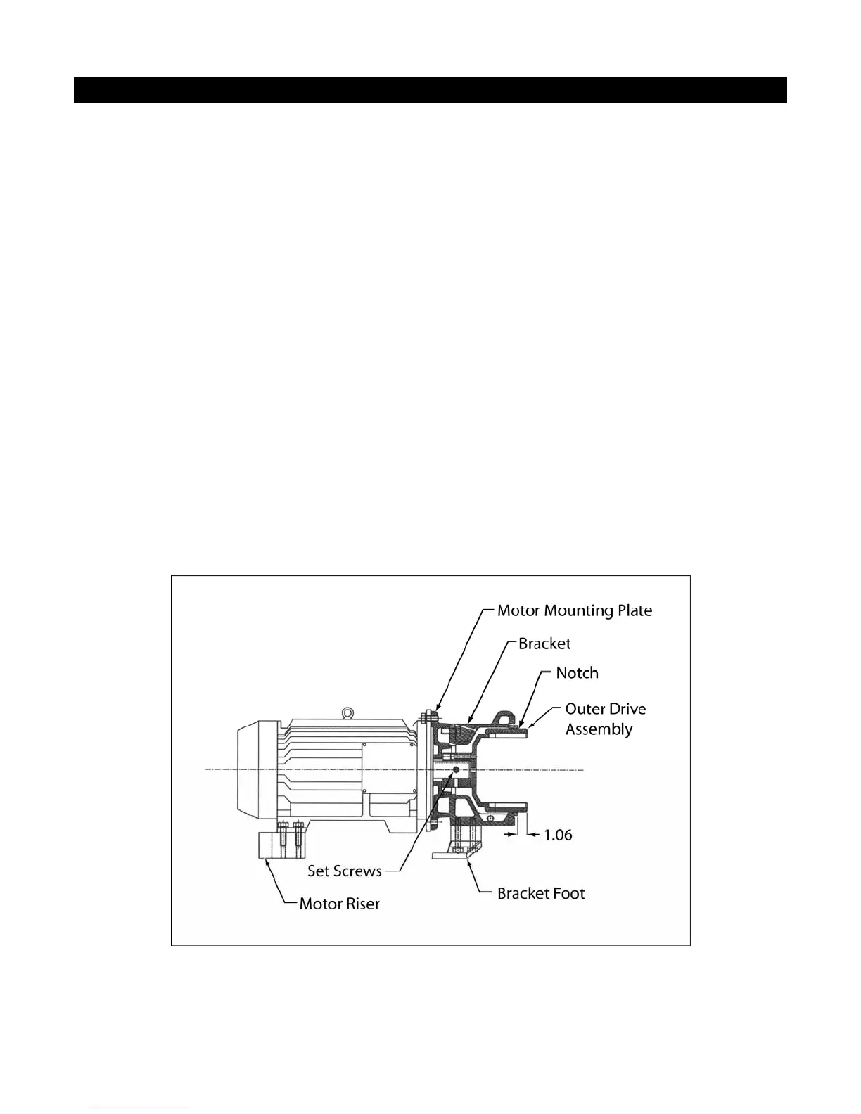
9-a. MOUNTING OUTER DRIVE TO MOTOR OR BEARING FRAME SHAFT
1. Place the motor vertically on the worktable or floor so that the shaft is pointing upwards. Be sure to
cover the work surface with corrugated cardboard or similar material to prevent damage to the fan
cover.
2. Place motor mounting plate(s), if required, onto the C-face of motor. Align the holes with the
threaded holes on the motor. (On motor frames 143/145TC and 284TSC, the motor mounting plates
bolt to the motor face holes.) See figure 9-1.
3. Place the bracket onto the motor mounting plate (or motor C face) and line up the bracket holes
with holes on the motor C-face and motor mounting plate(s). Use four (1/2"-13 UNC) socket cap
screws with lock washers to secure the bracket to the motor mounting plate. Tighten bolts to snug
only. Note that the holes on the motor mounting plate(s) are not tapped. The plates are actually
sandwiched between the bracket and the motor.
4. Back-out the two set screws on the hub of the outer drive magnet, and place the outer drive onto the
motor shaft. Position the outer drive so that the groove in the outer drive lines up with the end of
the bracket +1/16", -0" [+1.6 mm, -0 mm]. See Figure 9-1. Figure 9-2 shows the outer drive
position with respect to the motor mounting plate for reference. Tighten the set screws to 10 ft-lb
(13.6 N-m.) Install the 3/8” NPT pipe plug into the hole on top of the bracket or bearing frame.
This is to keep dirt out of the motor shaft area.
Fig. 9-1 Outer Drive Position with Respect to Bracket