62
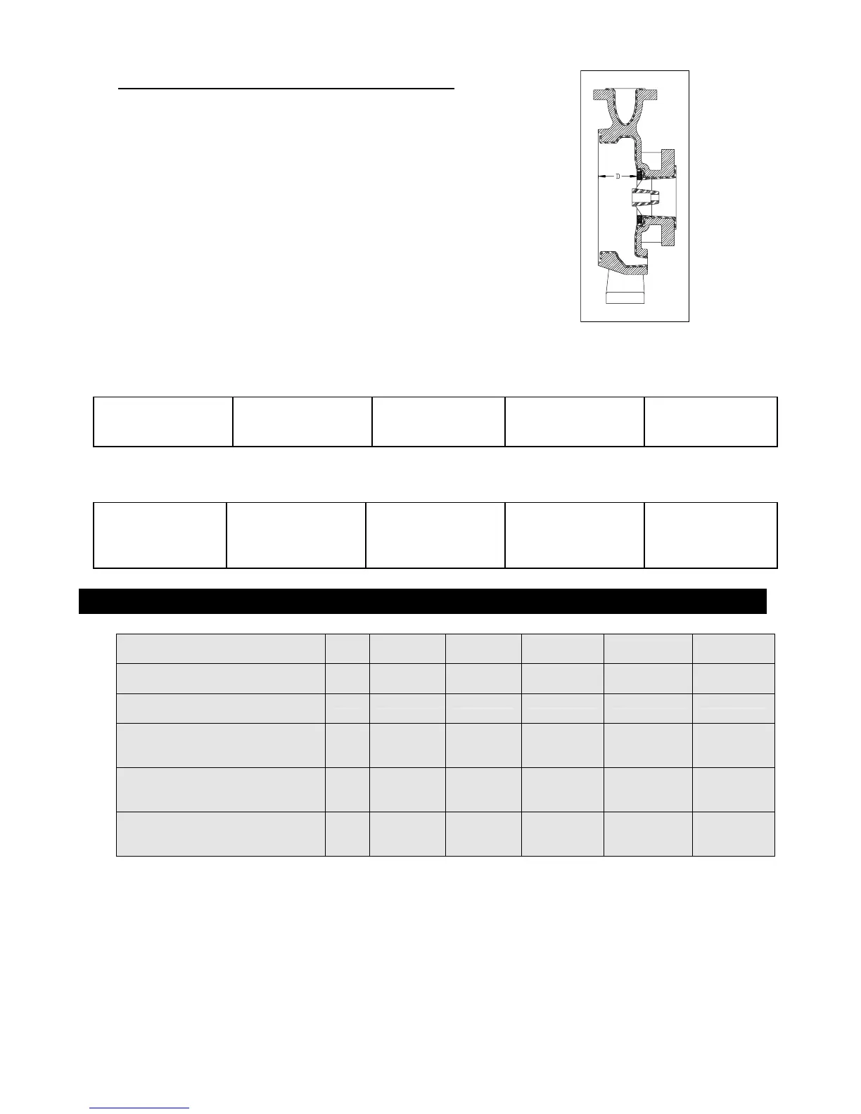
3. MEASURE THE DEPTH OF THRUST RING
After assembling the shaft support, measure the depth
between the thrust ring in the shaft support and the
end of casing. Refer to Fig.A2-3 and the table below
for the correct dimension. Measurements should be
taken on at least (4) locations to ensure that the thrust
ring is parallel with the face of the casing.
Fig. A2-3
K1516 K326 K436 K1518 K3158
1.5" x 1" x 6" 3" x 2" 6" 4" x 3" x 6" 1.5” x 1” x 8” 3" x 1.5" x 8"
D=2.425"+/- 0.015 D=2.563"+/-0.015 D=3.000"+/-0.015 D=2.850”+/-0.015 D=3.057"+/-0.015
Ki32160
50mm x 32mm x
160mm
D=74.3mm +/-.38
Ki50160
65mm x 50mm x
160mm
D=77.8mm +/-0.38
Ki65160
100mm x 65mm x
160mm
D=89.7mm +/-0.38
Ki32200
50mm x 32mm x
200mm
D=72.4mm +/-0.38
Ki40200
65mm x 40mm x
200mm
D=77.6mm +/-.38
ADDENDUM 2 – Inactive Parts
(Inactive)
A-drive, 10hp/3600, 5hp/1800
P2842A P2843A P2844A K0211 K0214
(Inactive)
B-drive, 15hp/3600, 7.5hp/1800
P2842B P2843B P2844B K0212 K0215
(Inactive)
C-drive, 30hp/3600, 15hp/1800
P2842C P2843C P2844C K0213 K0216
(Inactive) A-drive,
7.5 KW/3500, 3.75KW/1750,
5.5KW/2900, 3.0KW/1450
P2842A P2843A P2844A K0211 K0214
(Inactive) B-drive,
11KW/3500, 5.5KW/1750,
7.5KW/2900, 4.0KW/1450
P2842B P2843B P2844B K0212 K0215
(Inactive) C-drive,
22KW/3500, 11KW/1750,
18.5KW/2900, 9KW/1450
1
P2842C P2843C P2844C K0213 K0216