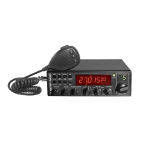
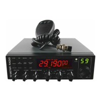
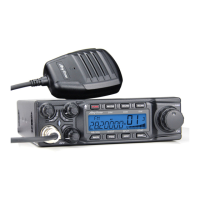
The AnyTone AT-5555 PLUS and AT-5555 PLUS/N are 10-meter amateur radio transceivers designed for demanding users, offering a blend of advanced technology, robust performance, and user-friendly features. The device incorporates SMT technology for enhanced stability, reliability, and quality.
Function Description:
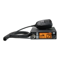
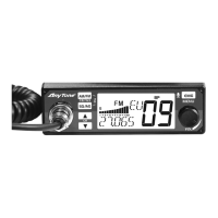
The AT-5555 PLUS/N operates in multiple modes, including PA (Public Address), CW (Continuous Wave), AM (Amplitude Modulation), FM (Frequency Modulation), USB (Upper Side Band), and LSB (Lower Side Band). It features a large LCD panel that displays frequency and various operational information, complemented by a dual-digital tube for channel display. The EL technology provides a clear backlight for the display.
The radio offers a wide range of programmable channels across six banks (A, B, C, D, E, F), with at least 60 channels per bank. Users can select frequency tuning steps of 10Hz, 100Hz, 1KHz, or 10KHz.
Key functions include:
- ECHO Function: Provides an echo effect for transmissions, with adjustable echo sound intervals.
- SQ, ASQ Function: Squelch and Automatic Squelch Control are available for FM and AM modes, helping to eliminate background noise.
- RF GAIN Adjustment: Allows users to adjust receiver sensitivity, crucial for both short and long-distance communications.
- RF PWR Adjustment: Enables adjustment of output power for AM and FM modes.
- SCAN Function: Automatically scans busy channels, with options to stop scanning based on signal detection (SQ mode) or after a set time (TI mode).
- RB Function (Roger Beep): Transmits an audio signal at the end of a transmission to indicate completion.
- NB/ANL Function (Noise Blanker/Automatic Noise Limiter): Filters to reduce background noise and reception interferences.
- DW Function (Dual Watch): Allows alternate monitoring of two channels.
- BEEP Voice Prompt (BP Function): Emits a beep sound when any key is pressed.
- +10KHZ Function: Shifts the frequency up by 10KHz.
- SWR, S/RF, DC Voltage Display: Provides real-time information on Standing Wave Ratio, signal strength/RF power, and supplied DC voltage.
- TOT Function (Time Out Timer): Automatically stops transmission after a programmable duration to protect the power tube from overheating.
- HI-CUT Function: Cuts out high-frequency interference, depending on reception conditions.
- EMG Call (Emergency Channel Call): Allows quick switching to a pre-set emergency channel.
- Key-Lock Function: Locks most keys to prevent accidental operation, except for PTT, BAND SWITCH, and MODE SWITCH.
- VOX Function: Enables voice-activated transmission, with adjustable sensitivity and delay time.
- CTCSS/DCS Code: Supports Continuous Tone-Coded Squelch System and Digital Coded Squelch for selective calling.
- RX Compander (Noise Blanker): Reduces receiver noise.
- Noise Gate Setting: Allows adjustment of microphone noise.
- RX Noise Reduction (NR): Specifically available on AT-5555PLUS/N models to reduce receiver noise.
- Microphone Type Compatibility: Supports both "electronic" and "dynamic" microphone types.
Usage Features:
The radio is designed for intuitive operation with a combination of knobs and keys on the front panel.
- OFF/ON/VOLUME (Inner Dual Concentric): Turns the radio on/off and adjusts the output volume.
- SQUELCH (Outer Dual Concentric): Eliminates receiver background noise in the absence of a signal.
- ECHO (Inner Dual Concentric): Controls the echo effect.
- TONE (Outer Dual Concentric): Controls the intervals of the echo sound.
- RF GAIN (Inner Dual Concentric): Adjusts receiver sensitivity.
- RF POWER (Outer Dual Concentric): Adjusts output power for AM and FM modes.
- BAND SELECTOR: Rotates to select different operating bands (A, B, C, D, E, F).
- MODE (PA/CW/AM/FM/USB/LSB): Selects the modulation mode for both transmitter and receiver.
- CLARIFIER: A frequency tuning knob with multiple operating modes:
- FIN (Fine Regulation): Fine-tunes the receiving frequency.
- RT (Real-Time): Regulates both transmitting and receiving frequencies.
- T (Transmit): Regulates only the transmitting frequency.
- PUSH Key: Can be configured for various functions, including COARSE tuning or changing the Frequency Tuning Step of the CLARIFIER knob.
- CHANNEL SELECTOR: Rotates to select desired channels, indicated by a numbered LED.
- RECEIVER/TRANSMIT INDICATOR: An LED that glows green during reception and red during transmission.
- FUNC Key: A multi-functional key. A short press activates secondary functions silk-screened under other buttons (e.g., FUNC+RB for BP function, FUNC+DW for LCD OFF). A long press (2 seconds) enters the Function Menu Setup.
- Microphone: Includes PTT (Press-To-Talk) switch, UP/DN keys for channel selection, and an AQ (Automatic Squelch Control) button. The AQ button can also be held for signal monitoring or pressed simultaneously with PTT to emit a single-tone for frequency adjustment.
Maintenance Features:
- SWR Adjustment: Critical for initial setup and whenever the antenna is repositioned. The manual provides detailed steps for adjusting SWR using either a built-in SWR meter or an external one, emphasizing the importance of a well-tuned antenna to prevent damage to the TX amplifier.
- RESET FUNCTION: Allows users to restore the radio to its original "factory settings" easily and instantly, which is useful for resolving accidental configuration changes or unwanted function activations. This process involves powering off, then pressing and holding FUNC and SCAN keys while powering on until "RES" appears on the LCD.
- Power Connection: The radio is protected against polarity inversion and requires a 12-volt DC power supply. For trucks with 24-volt systems, a 24/12 volt inverter is necessary. Users are advised to connect the power cable directly to the battery to minimize interference. The manual also warns against replacing the original 10A fuse with one of a different value.
- SWR Protection (TSR): An optional function that detects high SWR and automatically prohibits transmission, emitting a voice prompt and displaying "HI S" to warn the user. The radio automatically activates SWR Protection if the SWR value exceeds 20:1, even if the function is disabled.
- Power Supplied Voltage Protection (TDC): An optional function that monitors the supplied voltage. If the voltage goes beyond a pre-set range, the radio displays "DC LO" or "DC HI," prohibits transmission, and emits a beep prompt.
- LCD Display Customization (TLD): Users can set what information is displayed on the LCD during transmission, such as transmitting frequency (TF), SWR value (SR), supplied voltage (BAT), or remaining TOT time (TOT).