8
NOTE: SETTINGS ARE MADE THROUGH SUPPLIED POWERCHUTE SOFTWARE OR OPTIONAL SMART SLOT
ACCESSORY CARDS.
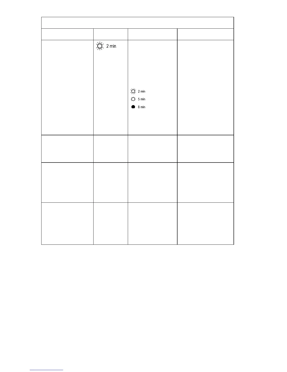
FUNCTION
F
ACTORY
DEFAULT
USER SELECTABLE
CHOICES
D
ESCRIPTION
Low Battery Warning.
PowerChute interface
software provides auto-
matic, unattended shut-
down when approximately
two minutes (by default) of
battery operated run time
remains.
Brightly lit: Low battery
warning interval is about
two minutes.
Dimly lit: Low battery
warning interval is about
five minutes.
Off: Low battery
warning interval is about
eight minutes.
Possible interval settings:
5, 7, 10, 12, 15, 18 min-
utes.
The low battery warning
beeps are continuous when
two minutes of run time re-
main.
You can change the warning
interval default setting
through PowerChute soft-
ware.
Synchronized Turn-on
Delay
0 seconds 20, 60, 120, 240, 480,
720, 960 seconds
The UPS will wait the speci-
fied time after the return of
utility power before turn-on
(to avoid branch circuit over-
load).
High Transfer Point 100V:
108VAC
120V:
127VAC
230V:
253VAC
100V:
110, 112, 114VAC
120V:
130, 133, 136VAC
230V:
257, 261, 265VAC
To avoid unnecessary battery
usage, set the high transfer
point higher if the utility volt-
age is chronically high and
the connected equipment is
known to work under this
condition.
Low Transfer Point 100V:
92VAC
120V:
106VAC
230V:
208VAC
100V:
86, 88, 90VAC
120V:
97, 100, 103VAC
230V:
196, 200, 204VAC
Set the low transfer point
lower if the utility voltage is
chronically low and the con-
nected equipment can tolerate
this condition.