SPECIFICATIONS
Item Specification
On-line Input Voltage Range
(default settings)
175 - 295 Vac
Automatic Voltage Regulation (AVR) +
12%
On-line Frequency Range 47 - 63 Hz (autosensing)
On-battery Waveshape Stepped Sine Wave
Maximum Load 1000 VA - 600 W
1500 VA - 865 W
Typical Recharge Time 8 Hours
Operating Temperature
0
o
to 40
o
C
(32
o
to 104
o
F)
Storage Temperature
-5
o
to 45
o
C
(23
o
to 113
o
F)
Operating / Storage Relative
Humidity
0 to 95% non-condensing
Size (H x W x D)
37.1 x 8.6 x 33.3 cm
(14.6 x 3.4 x 13.1 inch)
Weight 1000 VA 10.6 kg (23.4 lbs)
1500 VA 11.6 kg (25.5 lbs)
Shipping Weight 1000 VA 11.8 kg (26 lbs)
1500 VA 12.8 kg (28.2 lbs)
EMI Classification EN 50091-1, EN 60950, EN 50091-2,
EN 61000-3-2, EN 6100-3-3,
EN 55022 Class B
On Battery Run-Time See http://www.apc.com/product
TROUBLESHOOTING
Problem Possible Cause Corrective Action
Back-UPS will not switch on. Back-UPS not connected to AC power source. Ensure the Back-UPS is securely connected to an AC outlet.
Back-UPS circuit breaker “tripped”. Disconnect non-essential equipment from the Back-UPS.
Reset (push in) the rear panel circuit breaker. Switch on the
Back-UPS and plug in devices one at a time. If the circuit
breaker trips again, disconnect the device that caused the
breaker to trip.
Utility input voltage is out of range. Consider adjusting the transfer voltage and sensitivity. See
Transfer Voltage and Sensitivity Adjustment.
Back-UPS does not power
essential equipment during an
outage.
Equipment plugged into a Surge Only outlet. Unplug device from 'Surge Only' outlet and move to a
'Battery Backup' outlet.
Back-UPS operates on battery
although utility power exists.
Back-UPS circuit breaker “tripped”. Disconnect non-essential equipment from the Back-UPS.
Reset (push in) the rear panel circuit breaker. Switch the
Back-UPS on and plug equipment in one-at-a-time. If the
circuit breaker trips again, disconnect the device that caused
the breaker to trip.
Utility input voltage is out of range. Consider adjusting the transfer voltage and sensitivity. See
Transfer Voltage and Sensitivity Adjustment.
Back-UPS does not provide
expected backup time.
Back-UPS is heavily loaded. Unplug non-essential equipment (printers, scanners, etc)
from the Battery Backup outlets and plug into 'Surge Only'
outlets.
Back-UPS battery cartridge is discharged due
to recent power outage and has not had time to
recharge.
Charge the battery cartridge for 8 hours. Back-UPS runtime
is reduced until the battery cartridge is fully charged.
Battery has reached the end of its life. Replace battery cartridge (see Order Replacement Battery
Cartridge).
Red Replace Battery indicator is
flashing. Green On Line
indicator is on.
Internal battery cartridge is not connected. Connect battery cartridge (see Connect Battery Cartridge).
Red Replace Battery indicator is
on.
Battery has reached the end of its life. Replace the battery cartridge (see Order Replacement
Battery Cartridge).
Red Overload indicator is on or
flashing.
Connected equipment is drawing more power
than the Back-UPS can provide.
Move one or more equipment power plugs from Battery
Backup outlets to Surge Only outlets.
Green On Line indicator is on
and all front panel indicators are
flashing.
Internal UPS fault. Contact APC Technical Support (see Contact Information).
LIMITED WARRANTY
The standard warranty is two (2) years from the date of purchase. APC’s
standard procedure is to replace the original unit with a factory reconditioned
unit. Customers who must have the original unit back due to the assignment of
asset tags and set depreciation schedules must declare such a need at first contact
with an APC Technical Support representative. APC will ship the replacement
unit once the defective unit has been received by the repair department, or cross-
ship upon the receipt of a valid credit card number. The customer pays for
shipping the unit to APC. APC pays ground freight transportation costs to ship
the replacement unit to the customer.
In situations where the Back-UPS or connected equipment appears too
sensitive to input voltage, it may be necessary to adjust the transfer voltage.
This is a simple task requiring use of the front panel pushbutton. To adjust the
transfer voltage, proceed as follows:
1. Plug the Back-UPS into the utility power source. The Back-UPS will be in a
Standby Mode (no indicators lit).
2. Press the front panel pushbutton fully inward for 10 seconds. All indicators
on the Back-UPS will flash to acknowledge going into Programming Mode.
3. The Back-UPS will then indicate its current Sensitivity Setting, as shown in
the following table.
4. To select the Low Sensitivity setting, press the pushbutton until the yellow
indicator is flashing.
5. To select the Medium Sensitivity setting, press the pushbutton until the
yellow and red indicators (second and third from the top) are flashing.
6. To select the High Sensitivity setting, press the pushbutton until yellow and
both red indicators (bottom three) are flashing.
7. To exit without changing the Sensitivity Setting, press the pushbutton until
the green indicator is flashing.
8. Once in Programming Mode, if the pushbutton is not pressed within 5
seconds, the Back-UPS will exit Programming Mode; all indicators will
extinguish.
Indicators
Flashing
Sensitivity
Setting
Input Voltage
Range
(for utility
operation)
Use When
1
(yellow)
Low 156 - 300 Input voltage is extremely low or
high. Not recommended for
computer loads.
2
(yellow,
and red)
Medium
(factory default)
166 - 294 Back-UPS frequently goes On
Battery.
3
(yellow,
red, and
red)
High 176 - 288 Connected equipment is sensitive
to voltage fluctuations
(recommended).
TRANSFER VOLTAGE AND SENSITIVITY
990-1397A 1/04 Copyright © 2003 American Power Conversion All rights reserved.
APC, PowerChute Personal Edition, and Back-UPS are registered trademarks of American Power Conversion.
All other trademarks are the property of their respective owners.
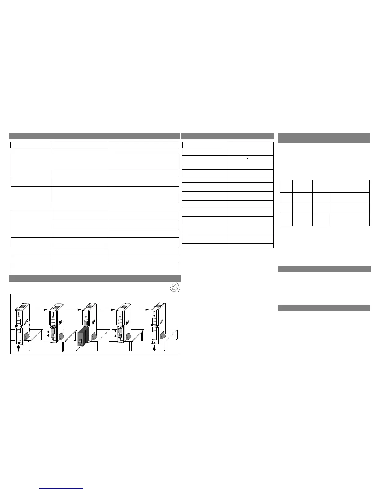
Battery
Cartridge
REPLACE BATTERY CARTRIDGE
ORDER REPLACEMENT BATTERY CARTRIDGE
The battery cartridge typically lasts 3-6 years, shorter if subjected to frequent outages or elevated temperatures. Order part number RBC33 for
1000 VA or 1500 VA models.
ADJUSTMENT
APC CONTACT INFORMATION
Online Technical Support .....................................isbtech@apcc.com
Web Site...............................................................www.apc.com
Worldwide ............................................................+1.401.789.5735
APC India .............................................................+91 80 221 3798 (3847)
Fax .......................................................................+91 80 221 3816
 Loading...