4
GENERAL INFORMATION
What is a beam detector?
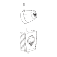
The XP95 beam detector is made up of a transmitter,
a receiver, an interface and, optionally, one or more
refl ectors.
The trans mit ter projects a beam of modulated infra-red
light to the receiver which converts it to an electrical
signal for process ing in the interface.
The trans mit ter and receiver are mounted so that the
beam will project ap prox i mate ly 0.3m to 0.6m below
and parallel to the roof or ceiling level at distances
up to 100m. The maximum lateral detection range is
7.5m either side of the beam. The interface is usually
installed at ground level.
How does a beam detector work?
When smoke is present in the beam path the light reg-
istered by the receiver is reduced by a level de ter mined
by the density of the smoke.
In the event of the smoke obscuring the light by a pre-
selected minimum level for a period of 8 to 10 seconds
a fi re signal is generated. The detection level can be
set to 25%, 35%, 50% or 65% to suit different environ-
ments, examples of which are given in the table in the
section 'Obscuration Level Setting' on page 6.
Automatic reset
If the beam detector has been in fi re or fault condition
it will au to mat i cal ly reset, once the fi re or fault is no
longer present. After a fi re condition there is a reset
delay of 30 seconds and after a fault a reset delay of
3 seconds.
Automatic signal strength
Over a period of time the light registered by the receiver
might be reduced by factors such as dirt building up
on the lenses of the detector.
The XP95 beam detector compensates for this auto-
matically in order to reduce the likelihood of unwanted
alarms. At the limit of compensation the beam detector
transmits a fault signal. In the event of a fi re being
detected when the beam detector has reached its
compensation limit, the fi re signal will override the
fault signal.
SYSTEM DESIGN
Positioning beam detectors
The XP95 beam detector must be positioned correctly
to minimise the detection time. The detection time
depends on
—the location of the beam detector within the
protected area
—the volume of smoke produced
—the con struc tion of the roof
—the ventilation arrangements
Particular areas where beam detectors should
not be fi tted include:
• spaces where very high levels of ambient
light are present in normal conditions
• areas where excessive amounts of dust,
smoke or water vapour are present as part
of the normal environment
• areas where rapid temperature changes
occur
• surfaces subject to vibration or movement
• buildings in which it is not possible to
mount the beam detector rigidly or align it
correctly
When deciding where to install the beam detector, you
need to think of the construction of the surface you
are fi tting it to and to possible changes as a result, for
example, of changing seasons. These surfaces must
be solid and should not be subject to movement.
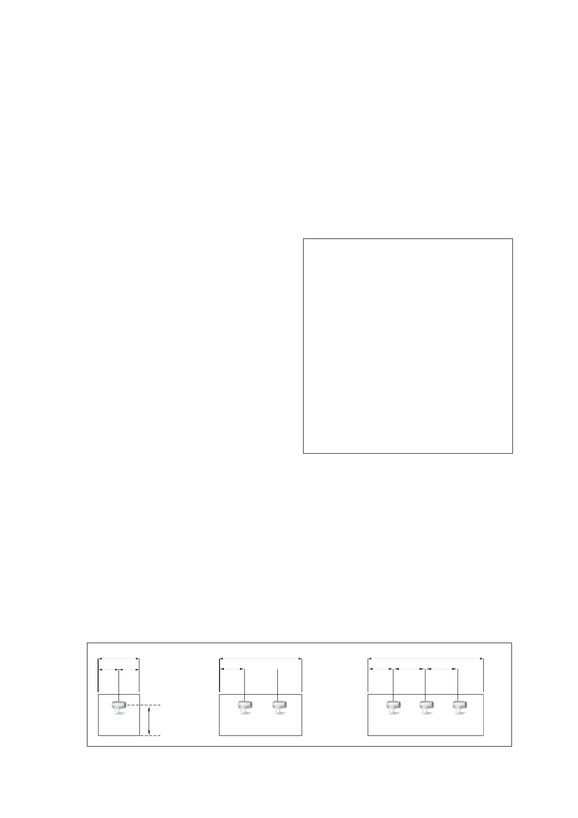
The maximum distance either side of the beam axis
is typically 7.5m for satisfactory detection under fl at
ceilings, providing a maximum total area coverage of
1500 square metres (15m x 100m). The maximum rec-
om mend ed installation height is 40m and the distance
between the beam and the ceiling should be within
0.3m and 0.6m (Fig 1). No more than 3m of the beam
path (measured from the centre of the beam) should
be within 500mm of any wall or partitions.
15m 30m maximum 45m and over
7.5m 7.5m 0.5m
min
0.5m
min
15m
15m
7.5m = max
beam to
wall
distance
0.5m = min
beam to
wall
distance
max = 40m
Fig 1 Positioning detectors under fl at ceilings—examples of three building widths
www.acornfiresecurity.com
www.acornfiresecurity.com