17
TECHNICAL DATA
Supply voltage 17–28V DC
Quiescent current (max) @ 24V DC
Receiver & interface 10.5mA
Transmitter 6.0mA
Alarm current (max) @ 24V DC
Receiver & interface 12.0mA
Transmitter 6.0mA
Fire alarm thresholds 1.25dB (25% obscuration)
1.87dB (35% obscuration)
3.0dB (50% obscuration)
4.55dB (65% obscuration)
Operating range 10m to 100m
5m to 45m with refl ectors
Tolerance to beam misalignment at 35% Transmitter ±1°; receiver ±4°
Optical Wavelength 880nm
Receiver/ interface cable type & max length Twin twisted pair (7/0.2), 1 pair A&B, 1 pair C&D
or
Screened 4-core (MICC, for example)
100m
Finish White
IP Rating 50
Operating temperature -20
0
C to +55
0
C
Sizes and weights
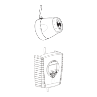
Interface 147 x 85 x 22 mm, 200g
Heads with Brackets 83 x 115 x 135 mm, 400g each
Part no. & size of refl ectors 29600-201, 100 x 100mm
For beam range 5–25m use 1 refl ector
25–35m use 4 reflectors, arranged as a square
35–45m use 6 refl ectors, arranged as a rectangle
Factory default settings
Alarm level 35%
Total obscuration option Fault
Alignment/normal setting Alignment mode
Address set 1
Spare parts
Part number Description
55000-265 Beam detector complete
29600-198 Spare interface
29600-199 Spare transmitter
29600-200 Spare receiver
29600-201 Refl ector
www.acornfiresecurity.com
www.acornfiresecurity.com