10
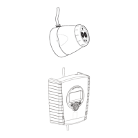
Aligning the beam detector
The beam detector incorporates alignment by means
of an LED in the receiver as this method is convenient
and can be carried out by one person without the need
for cables or a voltmeter.
The receiver is fi tted with a high-intensity red LED
which, in normal conditions, pulses when a fi re is
detected. During commissioning this LED may also
be used to facilitate beam alignment and cal i bra tion
(note that local light conditions must allow the LED to
be visible over the entire beam length, ie, up to 100
metres. During commissioning of the beam detector
the LED will be in one of the following states:
Calibrating the beam detector
The beam detector is calibrated by means of a poten-
tiometer in the transmitter. To access the potentiom-
eter, remove the small clear plug on the side of the
transmitter.
Use a small screwdriver to rotate the potentiometer.
Do not use excessive force.
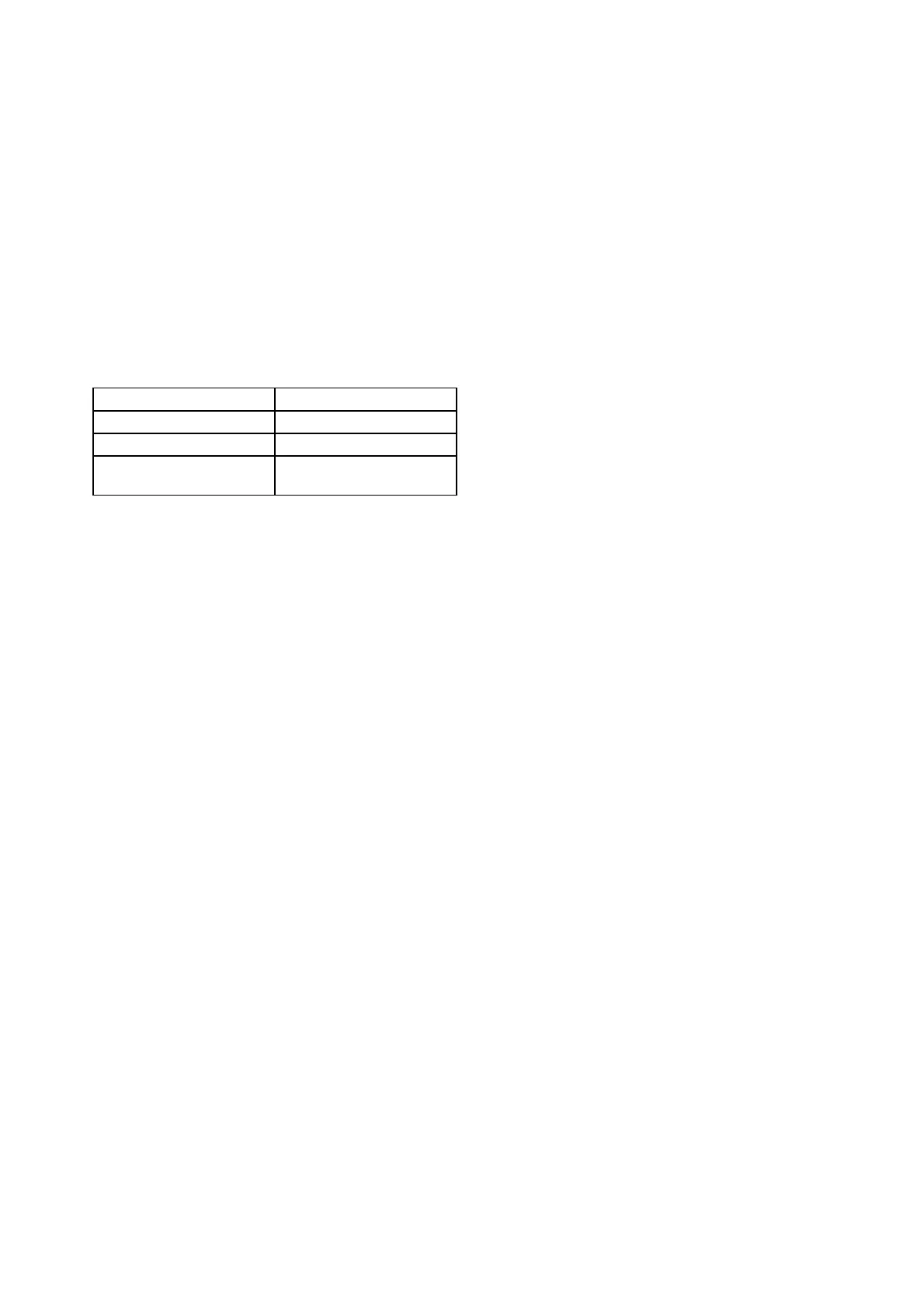
Receiver LED fl ash rate Status of alignment
Fast (4 fl ashes/sec ) Signal strength too high
No fl ash Optimum signal
Slow fl ash (1 fl ash/sec) Signal strength too low or
non-existent
www.acornfiresecurity.com
www.acornfiresecurity.com