11
Step by step guide to aligning and calibrating
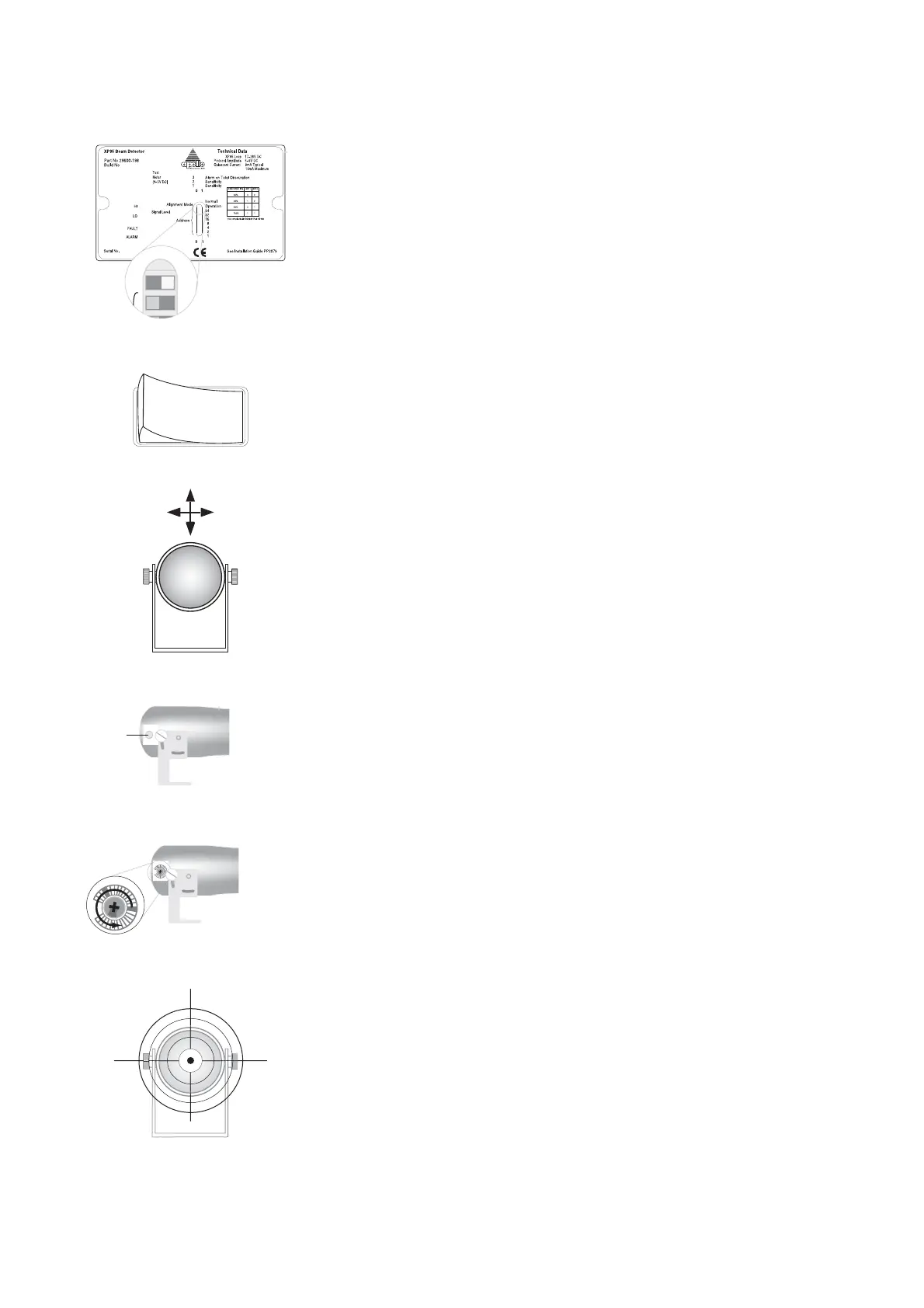
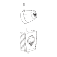
1. Check that the cables at the interface (Fig 4 on page 6) are correctly con-
nected and switch the interface to alignment mode.
2. Power up the beam detector.
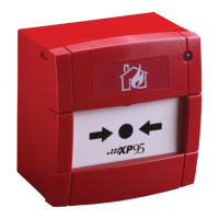
3. After fi tting the transmitter and receiver as described in point 3 on page
8, loosen the transmitter so that it can be moved with slight resistance up,
down, left and right.
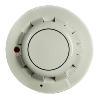
4. Remove the plug on the transmitter.
5. Using a 0 point cross-head or terminal screwdriver turn the potentiometer
fully anti-clockwise. This adjusts the transmitter power to maximum.
6. The transmitter must be correctly targeted at the receiver by a combination
of movements, up and down, right and left until the centre of the beam hits
the centre of the receiver.
Plug
Tx
Tx
100m
Rx
I
O
ON
OFF
Tx
www.acornfiresecurity.com
www.acornfiresecurity.com