12
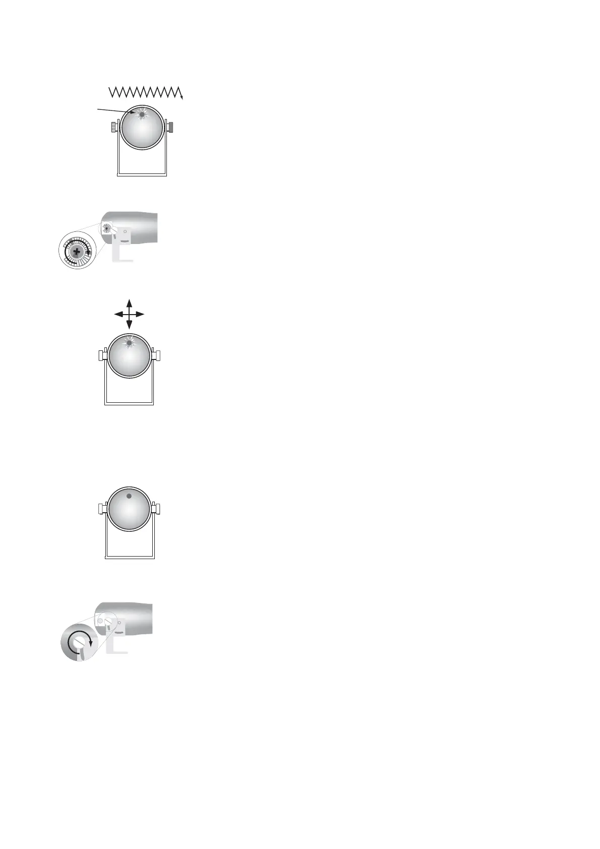
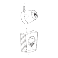
7. Move the transmitter left, right, up, down until the LED on the receiver
fl ashes fast. Hold the transmitter in this position.
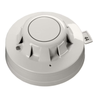
8. Reduce the signal strength by turning the potentiometer slowly clock-
wise until the receiver stops fl ashing.
9. Move the transmitter from right to left, in order to see if the receiver
LED can be made to fl ash fast again. If it can, repeat step 8.
Repeat this procedure but this time move the transmitter up and
down.
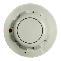
10.The beam detector is correctly aligned if there is no fl ash after carrying
out the movements described.
11. Tighten the securing bolts and screws of the transmitter, making sure
it does not move and replace the plug covering the potentiometer.
Failure to replace the plug may result in false alarms due to ingress
of contaminants.
fast fl ash signal too strong
slow fl ash signal too weak
no fl ash signal correct
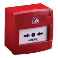
To confi rm the correct alignment of the detector move the transmitter
slowly up, down, left and right. Each movement should cause the LED
in the receiver to fl ash slowly. Leave in centre position with no LED
fl ashing.
Tx
100m
Tx
Rx
Receiver
LED
Rx
!
NO
FLASH
Rx
www.acornfiresecurity.com
www.acornfiresecurity.com