9
Retro operation
The XP95 beam detector may be confi gured so as
to operate in ‘retro’ mode*, in which the transmitter
and receiver are mounted adjacent and as close as
possible to each other, no more than 5mm apart. The
infra-red beam is projected onto refl ectors mounted on
the opposite wall, which refl ect it back to the receiver.
This t ype of operation is useful when access to the wall
opposite the transmitter is restricted or where wiring
is diffi cult. The refl ectors should be mounted at right
angles to the infra-red beam. See ‘Technical Data’ for
number of refl ectors to use. If more than one refl ector
is used, they should
be fitted so that
there are no gaps
between them.
A clear line of sight
has to be main-
tained between
the transmitter and
receiver at one end
and the reflectors
at the other end
of the area to be
protected.
The following
extra test should
be performed after installation for retro operation:
When the system is aligned and in normal operat-
ing mode, cover the refl ectors. The XP95 beam
detector should indicate ‘fi re’ or ‘fault’, depending
on the setting in the interface. (See section ‘Instal-
lation of interface’). If not, it is possible that the
signal has been returned via a surface other than
the refl ectors.
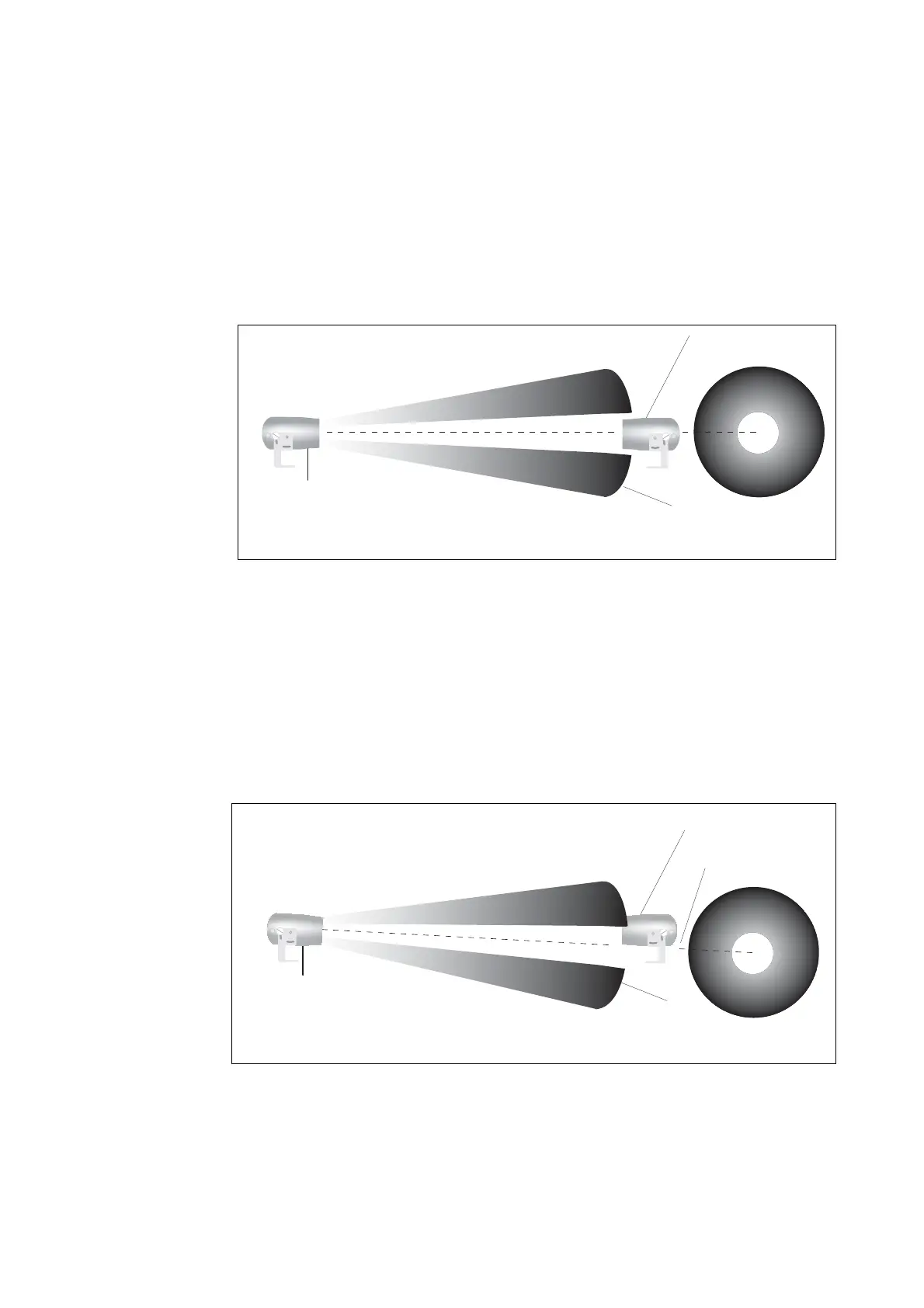
Alignment and calibration
The transmitter produces a conical beam of light which
is approximately 3 metres in diameter at a distance of
100 metres. The purpose of alignment is to ensure
that the centre of the beam is projected onto the centre
of the receiver (Fig 7).
The purpose of calibration is to ensure that the amount
of light sent by the transmitter is correct for the distance
between the transmitter and the receiver.
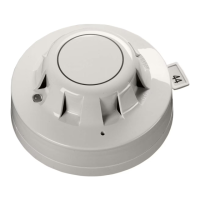
The accuracy of calibration depends on the accuracy
of alignment. The XP95 beam detector is tolerant, to
a certain extent, of alignment and calibration that is
not optimal, but misalignment may lead to faults at a
time subsequent to commissioning, perhaps because
structural movement in the building occurs (Fig 8).
The XP95 beam detector has been designed with ease
of commissioning in mind and is aligned and calibrated
using an LED.
*In retro operation smoke passes
through the projected beam twice;
the alarm level should therefore be
set to 65% obscuration.
Fig 8 Beam detector misaligned
receiver
light cone
transmitter
Side view of transmitter and receiver End view of receiver
centre of beam misses receive
receiver
light cone
transmitter
Side view of transmitter and receiver End view of receiver
Fig 7 Beam detector correctly aligned
www.acornfiresecurity.com
www.acornfiresecurity.com