1. DESCRIPTION
Device fitted with Aprimatic microprocessor designed to drive 2 motors with a maximum
power of 250 Watt each. Absorption in stand- by: 15 W.
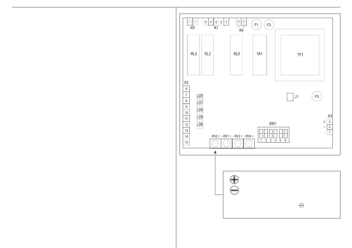
1.1 BLOCK DIAGRAM OF THE DEVICE
RV1 Approach speed trimmer
RV2 Reverse sensitivity trimmer
RV3 Pause time trimmer
RV4 Operating time trimmer
F1 Motor 5A fuse
F2 Network protection 200 mA fuse
F3 Accessory 24V output 500 mA fuse
SW1 DIP-SWITCHES
K1 Motor terminal board + mains voltage (IN)
K2 Signal/command terminal board
K3 Aprimatic exclusive accessory connection terminal
K4 Earth connection terminal board
K5 Courtesy light connector
RL3 Courtesy light relay
RL5 Motor relay
RL2 Direction relay
L5 Start LED relay
L6 Open safety photocell/close command LED
L7 Stop LED
L8 Photocell LED
L9 Limit switch LED
TF1 Transformer
J1 Slowing type
2. INSTALLATION
CAUTION - The product must only be installed by qualified servicing and/or installation
personnel.
CAUTION - The electrical system must comply with current regulations in the country
where the product is installed.
CAUTION - Always make sure that the mains power supply is turned OFF before
opening the container. Ensure that there is a good earthing system. Always
connect it to the relative terminals.
T3.EPS
= more sensitive = less thrust force
= less sensitive = more thrust force
N.B. If T3 is used with a hydraulic operator, set RV2 at the
end of the scale range towards .
Switch S6 to the ON position.