ilux Digital Bath with diverter installation instructions Page 13
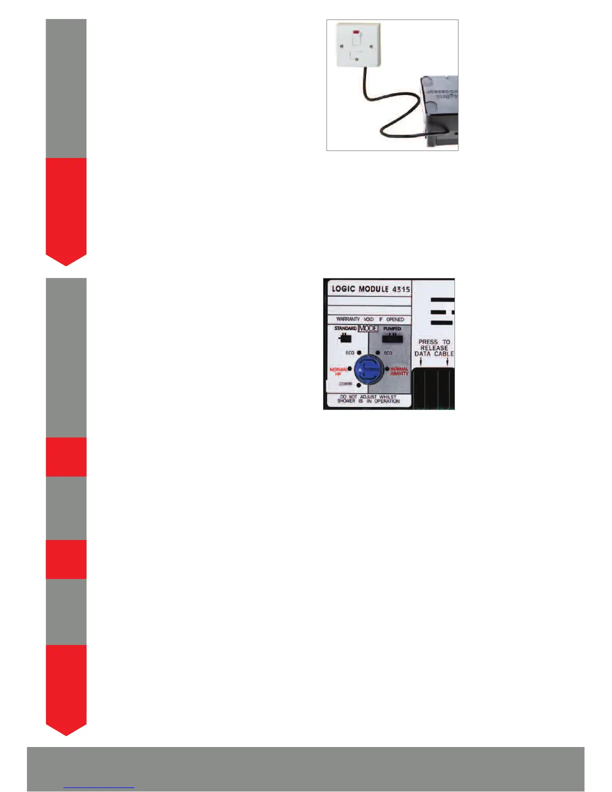
Connect the processor power lead to a double
pole 3 amp fuse switched spur incorporated in
the fixed wiring circuit, in accordance with
current wiring rules. Ensure that this is located in
an accessible, dry location and not in the
bathroom.
19
THIS APPLIANCE MUST BE EARTHED
We recommend protecting surface mounted cables in suitable approved
conduit to avoid the risk of damage from vermin.
The data cable and power lead should also be clipped in place with ‘P’ clips
or similar to avoid accidents.
!
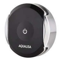
The Digital processors are supplied factory set
with the flow rate at either ‘NORMAL HP’ or
‘NORMAL GRAVITY’ mode depending on which
bath system has been ordered.
STANDARD PROCESSORS ON BALANCED
HP SYSTEMS:
Standard processors fitted to balanced high
pressure systems may be set to ‘NORMAL HP’ or for water economy ‘ECO’ modes.
N.B. As ‘ECO’ mode can be achieved by the ilux Digital controller,
we recommend the processor is set to ‘NORMAL HP’ mode.
STANDARD PROCESSORS ON COMBINATION BOILER SYSTEMS:
For Standard Digital processors installed on combi boiler systems, for optimum
performance we recommend setting the flow rate to the ‘COMBI’ mode.
20
N.B. The ‘ECO’ flow rate mode should not be selected for bath systems
fitted to combination boilers.
PUMPED PROCESSORS:
Pumped processors fitted to gravity systems may be set to ‘NORMAL
GRAVITY’ or for water economy ‘ECO’ flow rate modes.
N.B. As ‘ECO’ mode can be achieved by the ilux Digital controller,
we recommend the processor is set to ‘NORMAL GRAVITY’ mode.
WHEN MAKING ANY ADJUSTMENT TO THE PROCESSOR SETTINGS
THE POWER MUST BE ISOLATED.
!
!
!
!