13
1
Construct suitable connections at 150mm centres terminating in ¾” BSP male threads.
2
Ensuring adequate provision to allow the water to discharge safely to waste, turn on the supplies to flush the system
through. Attach pressure test equipment and pressure test the system in accordance with Water Supply Regulations.
3
Ensure the ¾” supply connections are temporarily capped to prevent any dirt of dust ingress into the pipe work during the
making good process. Remove the caps prior to connecting the shower valve.
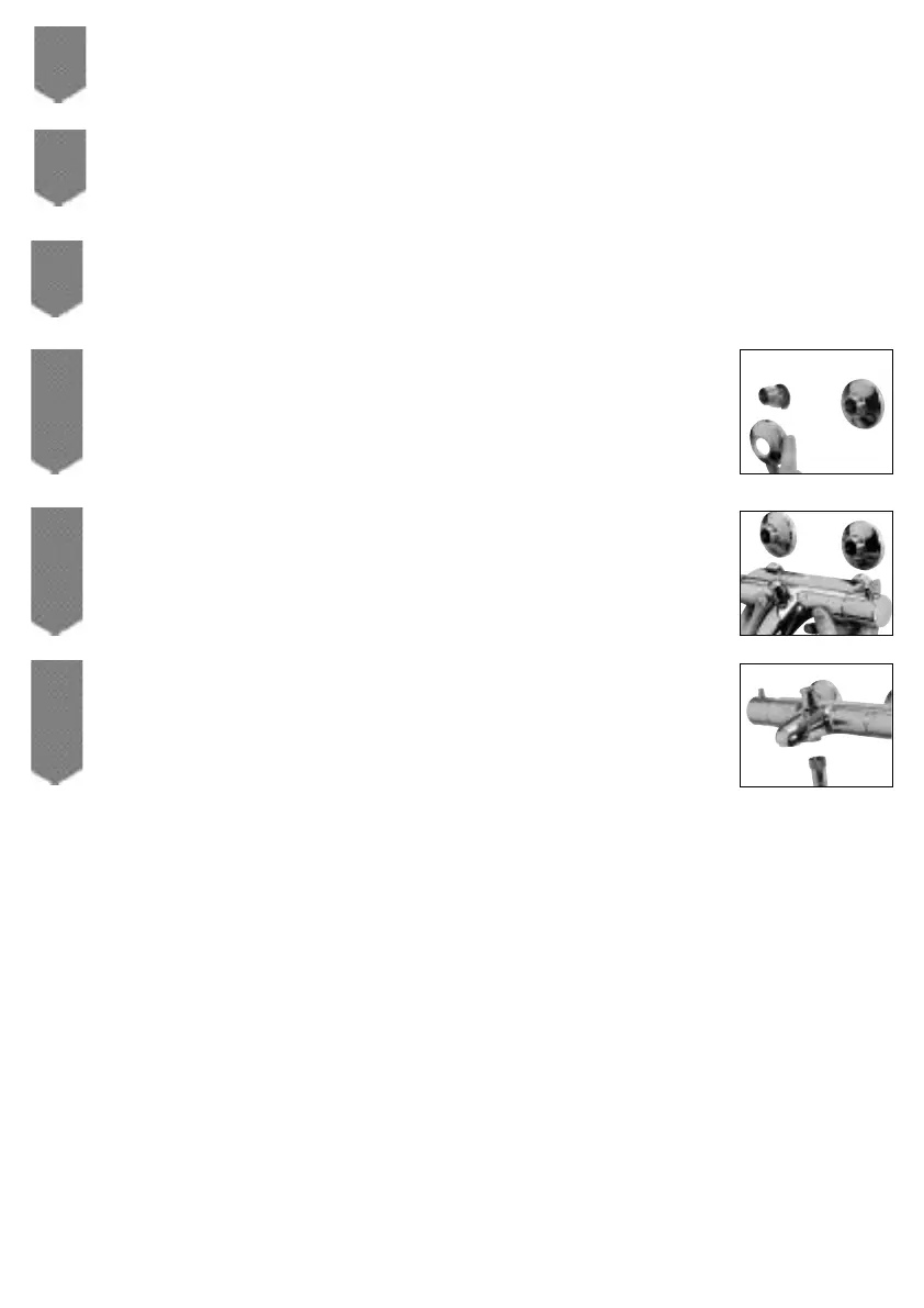
4
Inlet pipe cover plates are available separately from Aqualisa customer services or complete with
the easy fit fixing bracket. If required, apply a thin bead of mastic to the rear of the cover plates.
Place the cover plates onto the exposed ¾” threads flush with the finished wall surface.
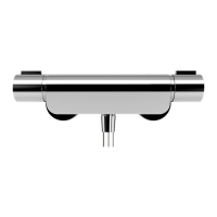
5
Ensuring the fibre washers are positioned within the valve inlets, offer the valve into position.
Tighten the fixing nuts using a suitable tool taking care not to overtighten.
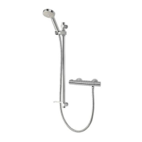
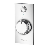
6
Turn on the supplies to the bath/shower mixer and turn the flow control knob on to flush the
system through. Turn off the bath/shower mixer.
If required, refer to the commissioning instructions on page 21 to adjust the maximum temperature override button position.
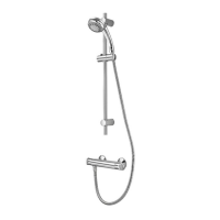
Follow the shower head system installation instructions on pages 15 to 18 to complete the installation.