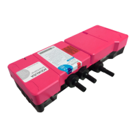
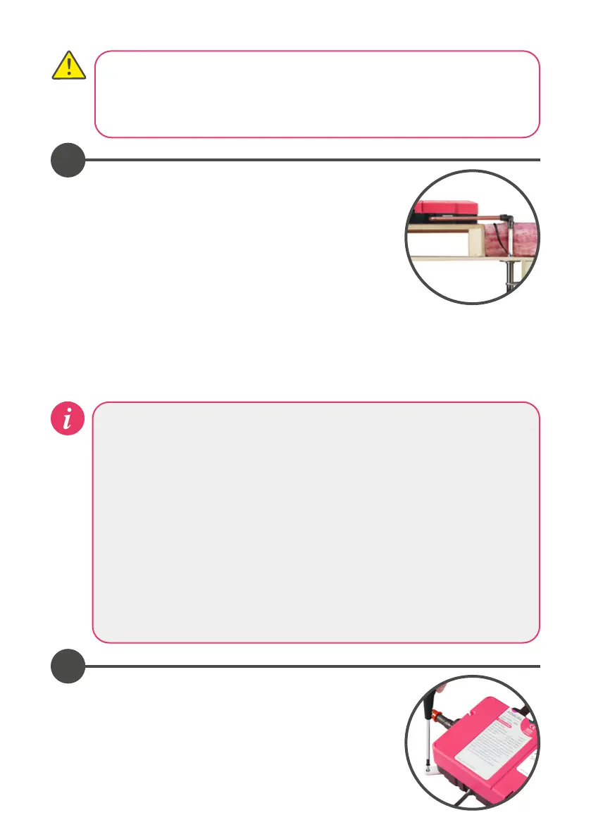
Place the Aqualisa SmartValve™ and diverter (where
supplied) on a solid mounting surface, and place the
fixing feet into suitable positions. Mark, then drill and
prepare suitable fixings securing to the mounting
surface using the screws provided (if suitable).
Choose the position for your Aqualisa SmartValve™ and
diverter (where supplied) as close to the controller as
possible. These may be sited in the roof space above the
proposed shower site, in the airing cupboard or behind a
screwed bath panel if more convenient. For information
regarding protecting the Aqualisa SmartValve™ and
diverter (where supplied) from cold/frost, contact Aqualisa
Customer Services or refer to the Aqualisa website.
Insulation material must not be placed under or on top of
the Aqualisa SmartValve™ and diverter (where supplied),
the location should be where freezing cannot occur. Please
refer to the system layout diagrams.
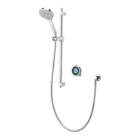
Exposed installation
example shown
3
4
The Aqualisa SmartValve™ and diverter (where supplied) MUST be sited in a
position that is safely accessible for servicing and commissioning purposes.
When fitted in a loft space, the route to, and the area around the Aqualisa
SmartValve™, and diverter (where fitted) must be boarded to ensure a safe
working environment.
The optimum position for the Aqualisa SmartValve™ and diverter (where supplied) is
in the roof space above the controller site to take full advantage of the ease and
speed of installation.
The distance between the Aqualisa SmartValve™ and the controller must be
within the range of the 10m data cable supplied. For dual-outlet models, the
diverter must be within the range of the 2m low voltage data cable connecting
it to the Aqualisa SmartValve™.
The inlet supply centres are 48mm.
Please note arrow on isolation valve to indicate direction of flow.
DO NOT use compression fittings on the inlet and outlet spigots as this will
invalidate the warranty if fitted.