AQUALISA SMARTVALVE
TM
SETUP
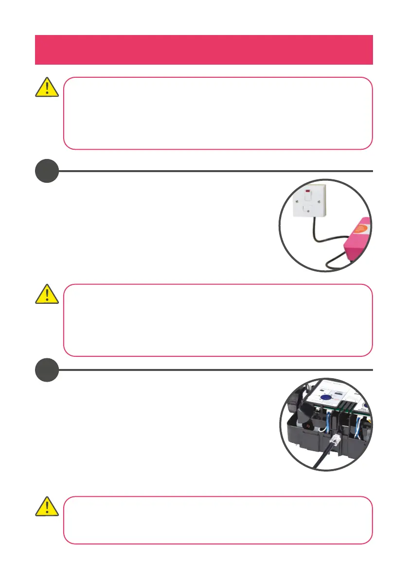
Connect the Aqualisa SmartValve™ power lead to a
double pole 3 amp fused switched spur incorporated
in the fixed wiring circuit, in accordance with current
wiring rules (refer to safety information section).
Ensure that this is located in an accessible, dry location
and not in the bathroom.
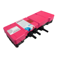
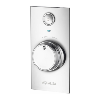
Loosen the single fixing screw on the top of the
Aqualisa SmartValve™ and diverter (where supplied)
then carefully tilt the lid up and o the location lugs,
and set the lid aside. Plug in the transparent connector
of the low voltage, 10m data cable into the socket
adjacent to the temperature adjuster as indicated
on the label. Feed the cable out of the Aqualisa
SmartValve™ ensuring it is correctly routed within the
data cable channel.
1
2
Before any electrical adjustment is attempted, the electricity supply must be
turned o at the mains switch.
Electrical installation may only be carried out by a qualified person.
All copper pipe work must be cross-bonded and connected to a reliable
earthing point.
THIS APPLIANCE MUST BE EARTHED
We recommend protecting surface mounted cables in suitable approved
conduit to avoid the risk of damage from vermin.
The power lead should also be clipped in place with ‘P’ clips or similar to avoid
accidents.
Divert models have product specific diverters, and the supplied diverter must
be used. If diverter is lost, damaged or separated from the main product
contact Customer Services for the correct replacement.