Aquatic Industries, Inc. 7
INSTALLATION INSTRUCTIONS
Note: The bath should remain in its shipping carton until time of installation.
1. Literature dimensions are for reference only. Installation dimensions should be taken directly from the tub. An ac-
make final connections and for servicing the pump and power panel. An additional access of 16’’ x 16’’ minimum
must also be provided for the blower motor and control box. Access may be through the wall or platform apron at
IT IS THE INSTALLER’S RESPONSIBILITY TO PROVIDE SUFFICIENT SERVICE ACCESS. MAKE ABSOLUTELY
CERTAIN THAT ACCESS PANELS AND/OR SERVICE OPENINGS ARE PROPERLY PLACED AND THAT ALL
POSSIBLE AREAS WHERE SERVICE MAY BE REQUIRED ARE ACCESSIBLE.
2. Install the drain fitting to the bath. Clearance may be needed for the drain by cutting away the subfloor (where
possible) or by blocking below the tub as may be required.
WARNING: FACTORY SKIRTS DO NOT ALLOW FOR BLOCKING UP OF THE TUB BASE. All blocking must
be solid and provide uniform support to the tub base.
3. Tub must rest entirely on all leveling feet. DO NOT SUPPORT THE WEIGHT OF THE TUB BY THE RIM. Lift unit
the unit by fastening the bottom feet to the sub floor with any construction adhesive caulk. For quieter operation
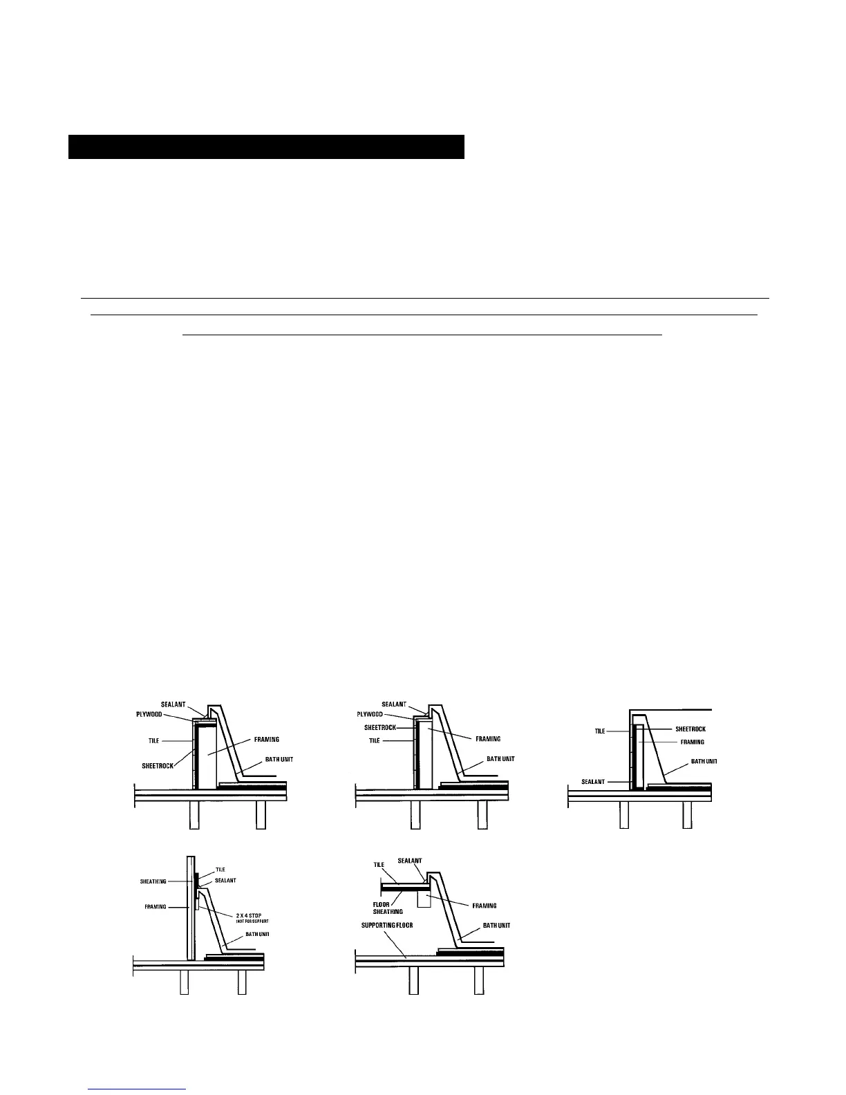
4. Frame out under the tub rim as shown in one of the illustrations below. NOTE: Due to the variety of installations
as required (see Diagram 1A, 1B and 1C
for wall sheathing material to run full length to the floor (see Diagram 1D). Install tub firmly against sheathing as
NOTE: Watertight installation of the drain and over flow is the installer’s responsibility. Drain and/or overflow leakage
is not included in the warranty of this product.
STRUCTURAL PREPARATION:
WARNING: ALL ELECTRICAL CONNECTIONS SHOULD BE MADE BY A LOCALLY LICENSED ELECTRICIAN.
1D Wall Installation 1E Sunken Installation
1B Ledge Installation - 2 1C Apron Installation
1A Ledge Installation - 1