4
Figure 1. AN-100-SW-R-5 Package Contents
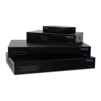
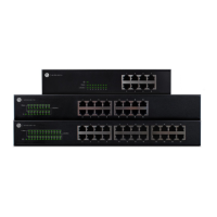
Table 1. Araknis Networks 100-series Family
Figure 10. AN-100-SW-R-8/16/24 Wall Mounting Option
7
5
14
Figure 2. AN-100-SW-R-8/16/24 Package Contents
Figure 3. Single Switch Network
Table 2. AC Electrical Requirements
Figure 12. AN-100-SW-R-8/16/24 Power Plug Connection
Figure 11. AN-100-SW-R-5 Power Plug Connection
7
9
15
15
15
Figure 4. Multiple Switches in Network
Table 3. Cable and Connector Recommandations
Figure 13. Application Diagram
9
16
16
Figure 6. AN-100-SW-R-5 On-Wall Mounting
Table 5. Link/Act LED Indicator
Figure 15. Side Layout
11
17
18
Figure 7. AN-100-SW-R-8/16/24 Rubber Foot Installation
Table 6. Power LED Indicator
Table 7. Specications
Figure 16. Rear Panel Layout
12
17
19
19
Figure 8. AN-100-SW-R-8/16/24 Rack Mounting Options 12
Figure 9. AN-100-SW-R-8/16/24 Rack Mounting Procedure 13
Figure 5. AN-100-SW-R-5 Rubber Foot Installation
Table 4. 1 Gbps LED Indicator
Figure 14. Front Panel Layout
11
17
17
FIGURES AND TABLES
Figures
Tables
 Loading...