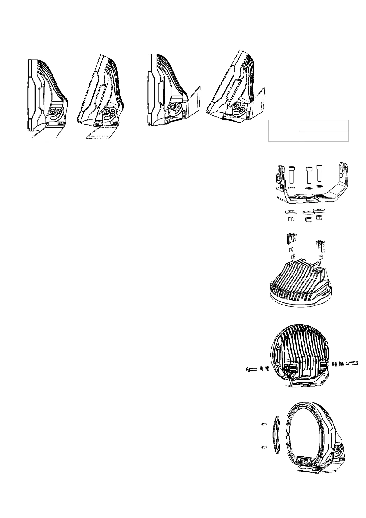
SETTINGS
M5 bolts 6.0 Nm /4.5 lbft
M8 bolts 22 Nm /16 lbft
TABLE 2.
INSTALLATION
Both vertical and horizontal orientations are possible as shown in Figure 3. Choose the required orientation and following the
steps below for installation and adjustment.
Vertical Orientation
Horizontal Orientation FIGURE 3
.
Step 1.
Place the mount onto the bull bar or flat mounting surface. Align with suitable
mounting holes on the bull bar. Where no holes are available, use mount to mark
new holes and drill accordingly including rust prevention.
Use three M8x30 socket head cap screws, M8 washers, M8 large washers and
M8 nyloc nuts to secure the mount as per Figure 4.
Insert the centre screw into the mount and keep loose to allow for adjustment.
Align the mount forward facing and ensure the light will illuminate straight down
the road. Insert the remaining two screws and tighten all screws to the torque
specified in Table 2.
Step 2.
Place the light body on a clean flat surface with the lens facing down. Insert the
two M8 square nuts into the light body rear cavity. Insert the nut covers to hold
the nuts in position as per Figure 5. Complete for the opposite rear cavity.
Step 3.
Place the light body into the mount and align the mount and light body holes as
shown in Figure 6. Insert four M8 washers, M8 spring washers and M8x30 Torx
drive button head screws. Loosely tighten to allow for adjustment later.
Step 4. (Adjustment).
Point the vehicle toward a flat wall and switch on the driving lights.
For horizontal adjustment, firstly remove the light body and then loosen the three
mount bolts. Refit the light body. Complete the horizontal adjustment and then
tighten the centre mount bolt to lock the correct mount position. Remove light
body from mount and tighten all three mount bolts. Reinstall the light body to the
mount as previously descripted, keep screws loose for vertical adjustment.
For vertical adjustment, measure the light output height on the wall and compare
with the driving light height on the vehicle. The two measurements should be
similar depending on user preference. Once satisfied with the height position, use
the security tool provided to tighten the four security bolts fixing the light body to
the mount.
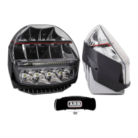
Changing the Bezel inserts.
Supplied with the light are two replacement bezel inserts. These bezel inserts
can be replaced to change the light appearance without effecting the water proof
seal. For each bezel insert, remove the two retaining screws. The bezel insert
can now be removed from the light as per Figure 7. Install the replacement bezel
insert noting the bezel inserts are handed and the correct bezel insert must be
installed. Insert the two retaining screws and tighten to the torque specified in
Table 2. Complete for the opposite bezel insert.
FIGURE 4.
FIGURE 5.
FIGURE 6.
FIGURE 7.
 Loading...