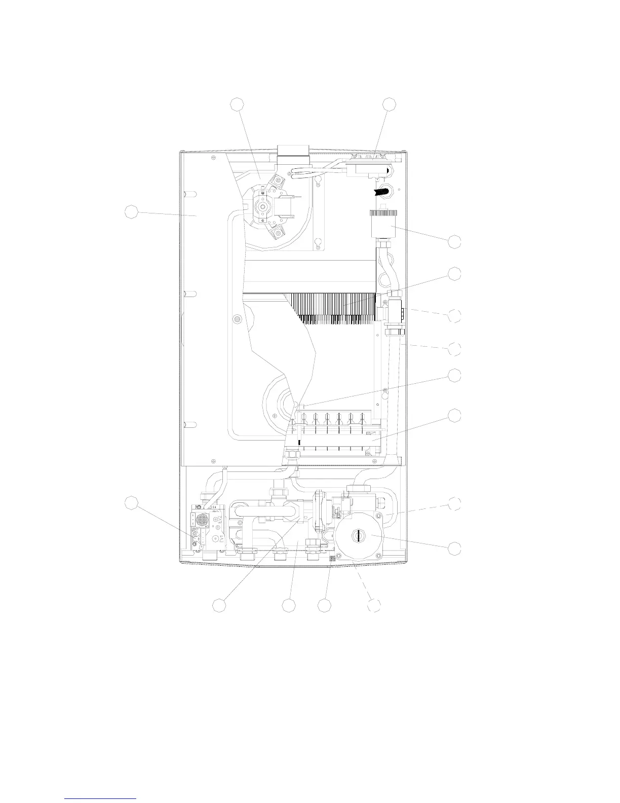
1.6 General layout of the main components of model
PIXEL 29 F
1 Air Pressostat
2 Discharge air valve
3 Limit thermostat (105°C)
4 Copper Primary Exchanger
5 Electrode of lighting and survey
6 Burner
7 Circulator
8 Gas valve
9 Valvola di sicurezza (3 bar)
10 Supply charge valve
11 Supply descharge valve
12 Sanitary water exchanger
13 Sonda riscaldamento
14 Hydraulic valve
15 Proof chamber
16 Fan
7
1
2
3
13
6
5
4
7
8
1014 11
9
12
15
16