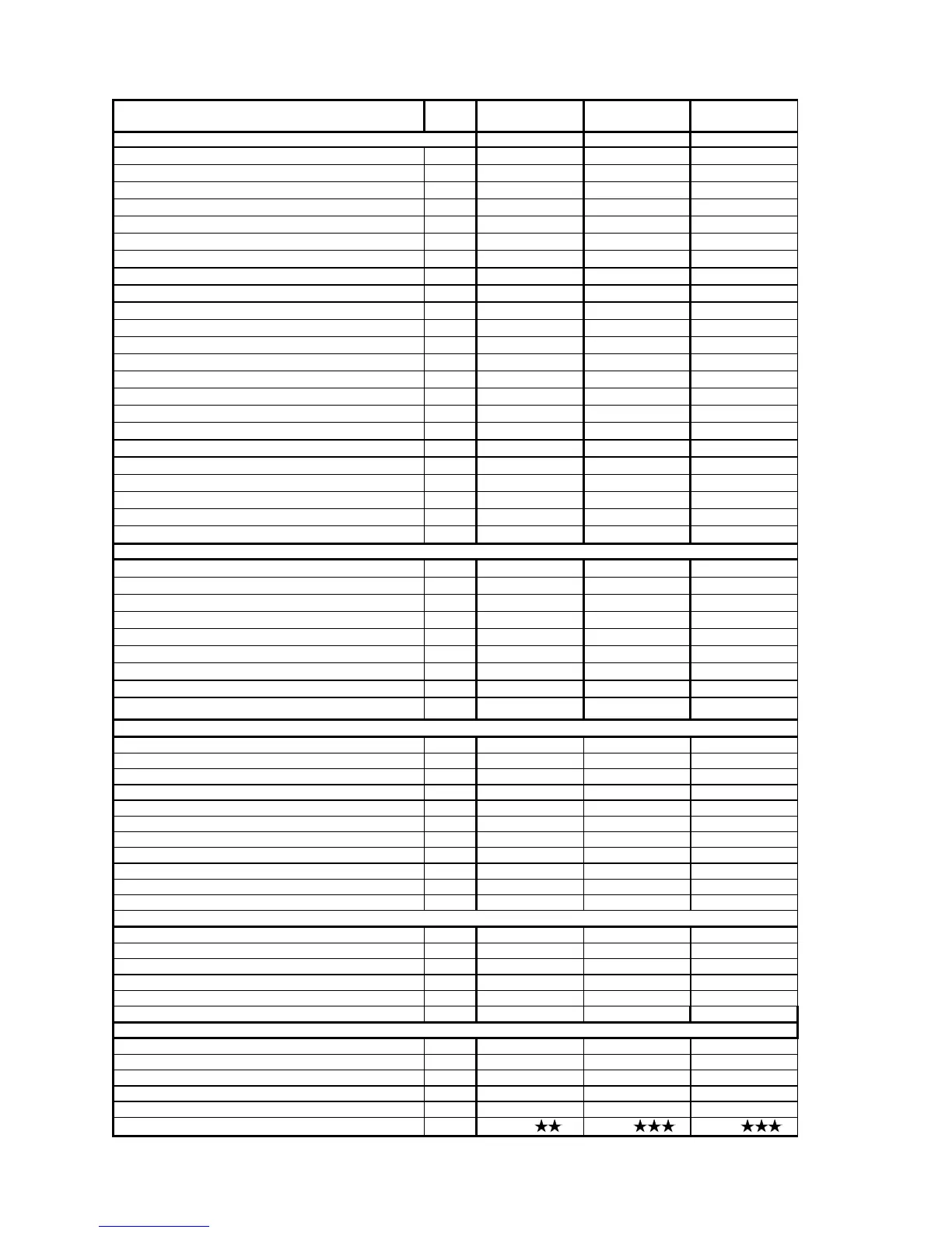
1.7 TECNICAL DATA
Size
PIXEL 25 N
PIXEL 25 F,
ES 25 F, IN 25 F
PIXEL 29 F
Type
B11BS C12-C32-C42-C52 C12-C32-C42-C52
Nominal Heat
KW 27 27 31,5
Nominal Heat
Kcal/h 23220 23220 27090
Useful Heat
KW 24,7 25,1 29,3
Useful Heat
Kcal/h 21200 21734 25194
Efficiency
% 91,3 92,9 93
Minimal Heat
KW 10,5 10,5 12,4
Minimal Useful Heat
KW 9,4 9,5 11,3
Efficiency at 30 % of Nominal Heat
% 89,5 90,7 91,2
Nominal Heat Gas Flow Metano G20 (2E+)
m
3
/h 2,855 2,855 3,331
Metano G25 (2ELL)
m
3
/h 3,320 3,320 3,874
GPL G30 (3+)
kg/h 2,128 2,128 2,482
GPL G31 (3P)
kg/h 2,096 2,096 2,445
Inlet pressure Metano G20 (2E+)
mbar 20/25 20/25 20/25
Metano G25 (2ELL)
mbar 20 20 20
GPL G30 (3+)
mbar 29 29 29
GPL G31 (3P)
mbar 37 37 37
Flue gas temperature
°C 115,3 126,7 131,4
CO
2
(G20)
% 6 7,7 7,6
Pondered NOx (according to EN 483 pars 6.2.2) mg/KWh ---- 119 (classe 3) ----
Losses of heat to the cover with burner ignited % 6,8 6,6 6,5
Losses of heat to the cover with burnernot ignited % 0,2 0,2 0,1
Losses of heat to the cover ((T = 50 °Cs) % 1,9 0,3 0,5
Gas flow rate Nm3/h 58,7 47,0 55,5
CENTRAL HEATING
C.H. Minimum Set point
°C 35 35 35
C.H. Maximum Set point
°C 90 90 90
Volume of water in the boiler
l 1,2 1,2 1,2
Volume of water of the expansion vessel
l 7,5 7,5 7,5
Pressure of the expansion vessel
bar 0,7 0,7 0,7
Least pressure in the primary circuit
bar 0,4 0,4 0,4
Maximum pressure in the primary circuit
bar 3 3 3
Maximum content of heating water
l 150 150 150
Available head at 1000 l/h of flow rate
mbar
230 230 330
Domestical hot water
Minimum set point °C 30 30 30
Maximum set point °C 60 60 60
Production continuous warm water (t = 25 °C) l/min 14,1 14,4 16,8
Production continuous warm water (t = 35 °C) l/min 10,1 10,3 12,0
Volume water (t = 30 °C in the first 10 minutes) l 117,8 120 140
Minimum flow l/min 2,5 2,5 2,5
Maximum pressure bar 8 8 8
Minimum pressure bar 0,5 0,5 0,5
Voltage l ---- ---- ----
Frequency V/Hz 230/50 230/50 230/50
Absorbed eletric power W 90 120 120
CONNECTIONS
Heating Inch 3/4" 3/4" 3/4"
Sanitary water Inch 1/2" 1/2" 1/2"
Gas Inch 1/2" 3/4" 3/4"
Height mm 720 650 720
Depth mm 300 260 300
Width mm 400 400 400
Lenght of flue gas ducts
Coaxial Ø 60 xes 100 mms m 3 4 4
Doubled Ø 80 mms m 16 30 30
Doubled Ø 60 mms m ---- ---- ----
Weight Kg 43 40 43
Degree of protection IP 44 IP4X 44
Homologation CE
0068 0068 0068
8