EN-13
Theory of Operation
The PA720 contains ve PCBs, the power amplier PCB,
pre-amplier PCB, lifter PCB, mains input PCB and front
panel PCB. What follows is an overview of each PCB as
well as any signals that go between the PCBs.
A note on standby modes
The PA720 has a number of dierent standby modes.
Modes are selected by simply sending a command over
the relevent control interface. To go back to the default
low power standby mode while the unit is powered up
press and hold the standby button on the front panel
for more than 3 seconds.
Standby Mode Note
RS232 NET
OFF OFF Lowest power mode.
Network module disabled
no RS32 or IP control.
ON OFF Network module disabled.
RS232 control availble, no
IP control
ON ON Network module enabled.
RS232 and IP control
availble.
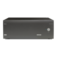
Power Amplier PCB - L281
The power amplier PCB consisits of 7 identical
channels.
All channels share a common main power rail of +/-
55VDC. The main output is powered with a switched
voltage +/-VLIFT, that will change between +/-30VDC
and +/-55VDC depending on the required output signal
level. All of which are supplied by the lifter PCB.
Irrespective of input type (RCA or XLR) the amplier is
fed via a balanced signal.
Pre-amplier PCB - L282
The preamp PCB has four main sections
• Host microcontroller (MCU).
• Network interface.
• Balanced (XLR) audio inputs.
• Single ended (RCA) audio inputs.
Host MCU
The host MCU IC400 controls all the functions of the
PA720 such as input type selection, muting, controling
the power supply, RS232 communications, interfacing
to the network module and monitoriong the amplier
status.
The MCU is powered by 3.3V generated locally from the
5V rail by REG500.
Network Interface
The network interface consists of an ethernet phy,
IC300, which is the interface to to the outside world. This
is controlled by the host MCU
XLR Audio Inputs
The XLR inputs are simply level shifted by a potential
divider, buered then sent via a relay to select between
XLR or RCA inputs to the power amplier via CON2.
NOTE: The XLR and RCA inputs are mutually
exclusive i.e only one type of input can be enabled
at any one time. You cannot mix input types.
RCA Audio Inputs
As the power amplier PCB requires a balanced input
the singled ended input is level shifted then then
converted to balanced.
Mains Input PCB - L283
The mains input PCB contains the main power relays
which control the power transfomer. The power
transformer has a soft start circuit where it is intially
connected to the main via a high current NTC to limit
the initial inrush current. This NTC is then bypassed once
the main PSU has stabilised.
The 5V and 3.3V standby rails are also generated here.
Lifter PCB - L284
The PA720 is a class G amplier and as such requires
two power rails for the output devices. The lifter PCB
contains the rectiers for both rails and also the circuitry
to switch between these rails depending on the output
level required by the amplier
 Loading...