12
B. Operation for TIG function
1) power switch
Turn on the power switch on the back panel and fan starts rotating; panel display is normal and power
supply indicator is light on; welder is successfully started.
2) TIG available:
Connect well the argon cylinder and turn on cylinder valve; adjust the flow meter to the according value;
Connect welding torch and earth clamp;
Pull the torch trigger and solenoid valve starts working; there will be argon out, also HF discharging at
the same time.
Please set welding current according to workpiece thickness.
Keep the distance between torch tungsten and workpiece at 2-4mm/0.08-0.16in; pull the torch trigger
and welder’s HF discharging noise will disappear as long as arc is successfully ignited; welding can be
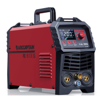
4. Insert the quick plug on the earth cable into
the “+” quick socket on the machine panel, and
tighten it clockwise. Clamp the workpiece with
the earth clamp at the other end of the earth
cable. (See Pic 9.)
Pic 9 Installation of Earth cable
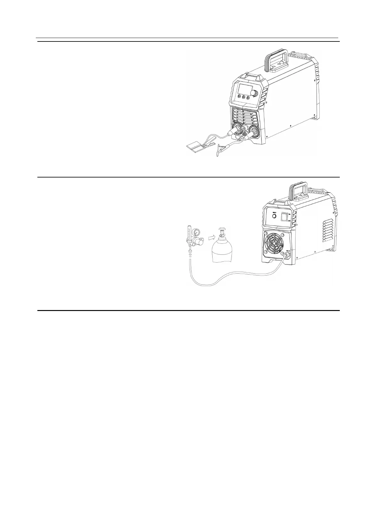
5. Gas connection: connect argon tube with
welder back panel’s brass mouthpiece tightly.
Air supply passage should include argon
decompressed flowmeter, gas hose; please use
a hose clamp or other fixing items to crew the
hose connection part so that to avoid poor
welding spot protection which is caused by gas
leakage or air admission. (Pic 10)
Pic 10 Gas connection
Digital Welder Expert, Know You More
https://www.arccaptain.com