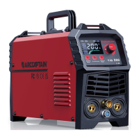
ARCCAPTAIN TIG200 Inverter Welding Machine
The ARCCAPTAIN TIG200 is an inverter welding machine designed for both TIG and MMA (Stick) welding processes. It is a 2-in-1 multi-process welding machine built with high-quality components and subjected to multiple industry-leading laboratory tests to ensure a great welding experience and performance. The machine features a unique design with an LED display panel for clear data reading, concise distribution, and convenient operation, along with warning indicators for normal and abnormal working conditions.
Function Description
The TIG200 operates as a constant current external characteristic welder, meaning the welding current remains stable regardless of arc length. It utilizes PWM technology and high-power IGBT switching elements to rectify AC110V/AC220V (50Hz/60Hz) voltage to DC310V, which is then inverted to 45KHz. This process, followed by voltage step-down and rectification, results in a stable welding current achieved through output current feedback and adjustment. The machine incorporates built-in MCU technology and an IGBT inverter, providing totally digital control for great and stable welding performance.
MMA/Stick welding features:
- Hot start: Facilitates easier arc ignition.
- Arc force: Helps prevent the electrode from sticking to the workpiece.
- Anti-stick: Reduces the likelihood of the electrode sticking.
TIG welding features:
- 2T/4T Operation: Allows for different trigger control methods, with 4T operation offering more control over the welding cycle, including up-slope and down-slope times.
- Current regulation: Enables precise adjustment of welding current.
- Post-flow adjustable: Controls the duration of shielding gas flow after the arc is extinguished, protecting the weld from atmospheric contamination.
- Down-slope: Manages the gradual decrease of welding current at the end of a weld to prevent crater cracking.
Additional functions:
- Fan-On-Demand cooling system: This intelligent cooling system operates only when needed, reducing noise, energy consumption, and the amount of contaminants pulled through the machine, thereby extending its lifespan.
- Safety protection: Includes over-current, over-voltage, and overheating protection circuits, which automatically stop the machine if set standards are exceeded.
- Remote control function: Supports foot pedal and analog torch (additional purchase required) for convenient remote adjustment of welding current.
Important Technical Specifications
Model: TIG200
Rated Input Power: Single Phase AC220V/AC110V ±15% 50Hz/60Hz
- The machine supports dual voltage input, automatically compensating for mains voltage fluctuations to keep the welding current within the specified range.
Rated Input Capacity: 7.8 kVA
Rated Input Current:
Rated Output Current/Voltage:
- @220V: TIG: 200A/18V, MMA: 170A/26.8V
- @110V: TIG: 140A/15.6V, MMA: 120A/24.8V
Rated Duty Circle: 40%
- This means the machine can operate at its rated output for 4 minutes out of every 10-minute cycle without overheating.
No-load voltage: DC 62 V
Output Current Range:
- @220V: TIG: 10-200 A, MMA: 10-170 A
- @110V: TIG: 10-140 A, MMA: 10-120 A
Post-flow Time: 0-10 seconds (adjustable)
- The time between arc ending and post-flow.
Down slope: 0-10 seconds (adjustable)
- The time taken from peak current to arc striking current.
Arc Ignition Type: HF (High Frequency)
- Ensures easy and reliable arc starting without touching the workpiece.
Enclosure Protection Class: IP21S
- Indicates protection against solid objects larger than 12.5mm and vertically falling water drops.
Insulation Grade: H
- Refers to the maximum operating temperature of the insulation materials.
Power Factor: 0.73
Efficiency: 80%
Dimension (LWH): 424135243mm / 16.695.39.56in
Weight: 5.3kg / 11.68lb
- The machine is portable and lightweight, equipped with a handle or shoulder strap for easy transport.
Usage Features
Panel Controls:
- Digital Display (88.8): Shows current parameter values, setting values for Down Slope and Post Gas, and error codes ("E61" for overload, "E10" for over current).
- Input Voltage Indicators (~110V, ~220V): Blinks to indicate the current input voltage.
- Control Mode Indicators (Panel, Remote): Blinks to show whether the welder is controlled by the panel or a remote device.
- Welding Mode Indicators (MMA, TIG 2T, TIG 4T): Shows the selected welding mode.
- Rotary Encoder Knob: Used to adjust parameters.
- Welding Mode Button: For switching between MMA, 2T, and 4T welding modes.
- Preference Button: For converting between Down slope, Post Gas, and Current settings.
- Control Mode Button: For switching between Panel and Remote control.
TIG Welding Operation:
- Connection: Connect the TIG torch's gas and electric connector to the machine panel and tighten clockwise. Connect the aviation plug of the TIG torch to its corresponding socket.
- Earth Cable: Insert the quick plug of the earth cable into the "+" quick socket and tighten clockwise. Clamp the workpiece with the earth clamp.
- Gas Connection: Connect the argon tube to the welder's brass mouthpiece. Ensure the air supply passage includes an argon decompressed flowmeter and gas hose, secured with a hose clamp to prevent leaks.
- Power On: Turn on the power switch on the back panel. The fan will start, and the panel display and power supply indicator will light up.
- TIG Welding: Open the argon cylinder valve and adjust the flow meter. Pull the torch trigger; the solenoid valve will activate, releasing argon and initiating HF discharge. Set welding current based on workpiece thickness. Maintain a 2-4mm (0.08-0.16in) distance between the torch tungsten and workpiece. The HF discharge noise will cease once the arc is ignited, and welding can commence.
- 4T Welding Logic: Provides a detailed sequence for arc initiation, current ramp-up (up-slope), main current, current ramp-down (down-slope), and post-flow, allowing for precise control over the welding process.
MMA Welding Operation:
- Connection: Insert the cable plug of the electrode holder into either the "+" or "-" welding current connection socket and lock by turning to the right. Similarly, insert the cable plug of the workpiece lead into the other connection socket. Polarity depends on the electrode manufacturer's instructions.
Maintenance Features
Daily Maintenance:
- Safety First: All maintenance requires professional knowledge and should only be performed by licensed operators. Ensure the power supply is cut off and wait 5 minutes after powering off before uncovering the machine to avoid electric shock or burns.
- Visual Inspection:
- Front Panel: Check for damaged or loose components, tightened output quick sockets, and ensure the abnormity indicator is off.
- Back Panel: Verify the input power cable and buckle are in good condition, and the air intake is unobstructed.
- Cover/Chassis/Side Plates: Check for loose bolts or screws.
- Routine: Observe the machine enclosure for color fading or overheating. Listen for normal fan sounds and check for abnormal smells, vibrations, or noises.
- Cable Inspection:
- Earth Cable: Ensure grounding wires (workpiece GND and machine GND) are tightened.
- Welding Cable: Check for worn insulation, exposed conductive parts, and proper connection to the workpiece.
- Gas Hose: Verify tight connections, hose clamps, and absence of wear or leakage.
Periodic Maintenance:
- Qualified Professionals: Periodic checks must be carried out by qualified professionals.
- Power Off: Always shut down the switching box and the welding machine before periodic checks to prevent injury.
- Capacitor Discharge: Wait 5 minutes after powering off to allow capacitors to discharge.
- Periodic Check:
- Inner Circuit: Periodically check for good inner circuit connections (especially input plugs and other components). Tighten loose connections and remove oxidization with sandpaper if present.
- Cable Insulation: Inspect all cables for dilapidation and rewrap or replace as needed.
- Static Protection: Wear antistatic devices or touch the metal enclosure to discharge static before contacting internal wiring or PCBs to prevent damage to semiconductor components.
- Dry Environment: Avoid rain, water, and vapor infiltration. If damp, dry the machine and check insulation with an ohmmeter before use. Store in original packing in dry places if not used for extended periods.
- Cleaning: Clean the machine interior during periodic checks. Generally, perform checks every 6 months, or every 3 months in dusty or oily environments.
- Corrosion: Clean plastic parts with neutral detergent.
Failure Diagnosis and Troubleshooting:
- Pre-Maintenance Checks: Before troubleshooting, verify input voltage (220V/110V±15%), correct and tight connections of input and welding cables, normal gas circulation (pure argon, adjusted flow), and secure connections of all PCB terminals.
- Common Issues and Solutions:
- Power supply indicator off, fan off, no current: Check power switch and electricity input.
- Power supply indicator on, fan off, no current: Check DC24V supply, main relay, and DC15V power supply.
- Fan works, unstable/uncontrolled output current: Check front panel potentiometer, electrolytic capacitor, and connections.
- Fan works, abnormity light off, no welding output: Check torch trigger contact, DC15V power supply, drive wire, panel potentiometer, and output terminal connection.
- Fan works, abnormity light on, no welding output: Could be over-current or over-heat protection (restart after cooling), failed thermistor, or failed IGBT on inverter PCB.
- Black welding spot: Ensure normal argon outlet, sufficient argon flow (5L/min generally), good sealing, gas purity, and absence of strong airflow.
- Poor protection for welding bead: Do not move the torch immediately after welding; prolong post-flow time.
- Hard arc ignition, frequent current interruption: Change tungsten, remove oxidation, prolong post-flow time, adjust tungsten electrode discharge distance (around 0.8mm).
- Unstable welding current: Check power network and use different input cables if strong interferences are present.
- No HF discharge: Check OCV (DC62V), torch trigger control loop (LED3 should light up), and HF control loop.
- Display E10: Restart machine, check flat cable between front and top PCBs. If issue persists, contact distributor.
- Display E61: Check thermistor connection to control board; replace if damaged.