EasyManua.ls Logo

Arcom Digital Quiver XT User Manual

Arcom Digital Quiver XT
80 pages
To Next Page IconTo Next Page
Page #1 background imageLoading...
Page #1 background image
Quiver XT User Guide
Quiver XT and XT-UB v.1.3.1
Firmware release XT4.19 and above
Q-browser release 5.0.0.11 and above
12/04/18
This document describes the operation and feature set of the Quiver XT.

Table of Contents

Question and Answer IconNeed help?

Do you have a question about the Arcom Digital Quiver XT and is the answer not in the manual?

Arcom Digital Quiver XT Specifications

General IconGeneral
BrandArcom Digital
ModelQuiver XT
CategoryMeasuring Instruments
LanguageEnglish

Summary

Introduction

Quiver Functional Overview

Navigation Buttons

Power ON/OFF

How to turn the unit on, off, or put it into standby mode.

<ENTER> Button

Used to confirm changes and enable functions.

Exit Button

Press to exit menu items; some screens require 'Back' soft key.

Cursor and Function Keys

Keys for scrolling, switching functions, and interacting with displayed info.

Inputs and Outputs

F-Ports

F-Type RF ports that change purpose based on menu selection.

Forward/Tx/Antenna Port

Connects to forward test port at amplifier or fiber node.

Return/Rx Port

Serves as input or output for calibration signal.

Battery Charger Input

Connector for charging batteries via AC or car charger.

USB 2.0 Port

Connects to PC for picture transfer and firmware updates.

Batteries

Startup Procedure

Brightness and Audio Control

Settings Overview

Settings – General

Contains FSK data carrier/frequency info and background color settings.

Setting Up FSK Data Carrier Frequency

Background Color Setting

Settings – Measurement

Setting Operation Standards

Set TV standard for proper operation in spectrum analyzer/leak detector modes.

Distance Scale Setting

Return Band Configuration

FWD Scan List Selection

Sweep Profile

Settings – Calibration

Quiver XT Operation Modes

CPD Radar Mode

Calculates time distance to CPD sources and displays peaks on LCD screen.

Passive CPD Radar

CPD Radar Connection Diagrams

Node Connection – Single Output Amp/Fiber Node

Diagram for connecting at single output amps/fiber nodes with close splitters/taps.

Node Connection – Isolation at Fiber Node

Amplifier Connection for CPD Location

Tap and Splitter Connection for CPD Location

End of Line CPD Identification

Using CPD Radar in Local View

Selecting CPD Detection Filter Bandwidth

Selecting Noise Suppression

Noise Compression Settings

Using the CPD Marker Option

Zoom Mode in Passive Radar

Filtering of Analog Channels

Active Radar Mode Warning

NTC TDR Functionality

NTC TDR Connection to Amplifier

NTC TDR Connection to Line Passive

Connecting TDR to a Line Passive

Connecting TDR to an Amplifier

Connecting TDR to a Length of Cable

Using the TDR

Check Spectrum

View return spectrum to confirm spread spectrum ranging pulses are not visible.

TDR Settings – Velocity of Propagation (VOP)

TDR Cable Type Selection

Recommended TDR Signal Level

TDR Run Modes

Spectrum Analyzer/Signal Level Meter Modes

Return Spectrum Analyzer Mode

Use the return spectrum analyzer with 100 MHz bandwidth.

Return SA Mode Settings

Select Minimum Frequency

Procedure to set the minimum frequency using the numerical keypad.

LNA – Low Noise Amplifier

Reference Level Change

Scale Change

Marker Functionality

Using Max Hold

Hold Feature

Saving a Spectrum Analyzer Trace

Saving a Spectrum Trace

Forward SLM/Spectrum Mode

Examples of Actual FWD Spectrum Signals

QAM Demodulator Mode

Using the Save Trace Option

Recalling a Trace

Clearing Traces

Downloading Traces

Using CPD Radar in Headend View

Calibrator Mode (QVR-XT Only)

Calibrator Connection Diagrams

Nodes Calibration

Diagram for Node Calibration, recommended for fiber nodes.

Alternative Node Calibration

Using Calibrator Mode

Setting Up the Data Carrier Frequency

Node ID Adjustment

Setting the Signal Output Level

Calibrating a Fiber Node

Turning Calibrator Output Signal ON and OFF

Node Scanning Messages

Error Handling and Calibration Confirmation

Leakage Detector Operation

Leakage Detector Frequency Selection

Max Hold Leak Level

Saving and Recalling Leakage Trace

RTN Simple Sweep Generator

Sweep Profiles

Fixed Sweep Profile

Creating a Fixed Sweep Profile

Transferring Fixed Sweep Profile via Q-Browser

Quiver Navigator App

Loading Maps into Quiver Navigator App

Steps to download and install the app and load maps.

Map Download and Installation

QR Codes for Fault Location

QR Code Function Activation

Using QR Code with Mobile Quiver Navigator App

QR Code Usage for Device Connection

Corrected Device Return Loss Values

Application Map Features

TDR Response Peaks Analysis

Select specific TDR peak numbers for detailed analysis.
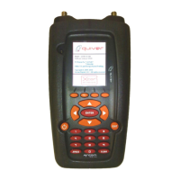
Map Displays Overview

Changing the Quiver-XT Battery Pack

Changing the Q-AMP Battery

Quiver-XT-UB Specifications

Mode Specifications

Q-AMP 5/40 and Q-AMP-5/70 MHz Specifications