EN - 14
1. Stop engine, remove key and close fuel
valve. Allow unit to cool.
See Figure 12.
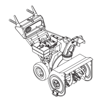
2. Tip unit back onto engine guard. DO NOT
tip further than engine guard allows or oil
may leak out of engine.
3. Remove six hex bolts, washers and top
locking flange nuts securing each paddle
to center plate and side plates. Discard all
parts.
IMPORTANT: Do not remove center plate.
4. Position new paddles with wear indicator
holes on the left side as you face the unit.
5. Install spacers into paddle holes and
secure paddle with new hex bolts and
nuts.
6. Tighten nuts to 5.6 – 10.2 N•m (50 – 90
lb-in). DO NOT overtighten.
7. When both paddles are installed, rotate
auger paddles by hand. Ensure that
paddles do not rub on housing and are
tightly attached.
8. Return unit to operating position.
9. Remove slack from auger cable. See
Adjust Auger Cable on page 14.
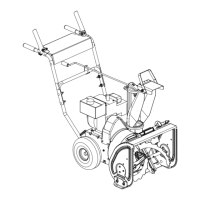
ADJUST AUGER CABLE
See Figure 13.
1. Stop engine, remove key and close fuel
valve.
2. Slide plastic sleeve up to auger control
bar.
3. Insert Z-hook into appropriate hole in
adjustment bracket. When auger control
bar is disengaged, there should minor
slack in cable and no tension.
4. Engage auger control bar to ensure
proper operation. There should be no
excessive tension on cable.
5. Lower plastic sleeve.
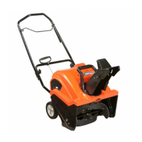
Figure 11
1. Wear Indicator Hole
1
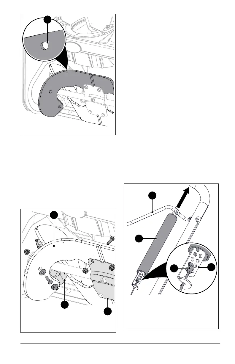
Figure 12
1. Auger Paddle
2. Side Plate
3. Center Plate
1
2
3
Figure 13
1. Auger Control Bar
2. Plastic Sleeve
3. Z-hook
4. Adjustment Bracket
1
2
3
4