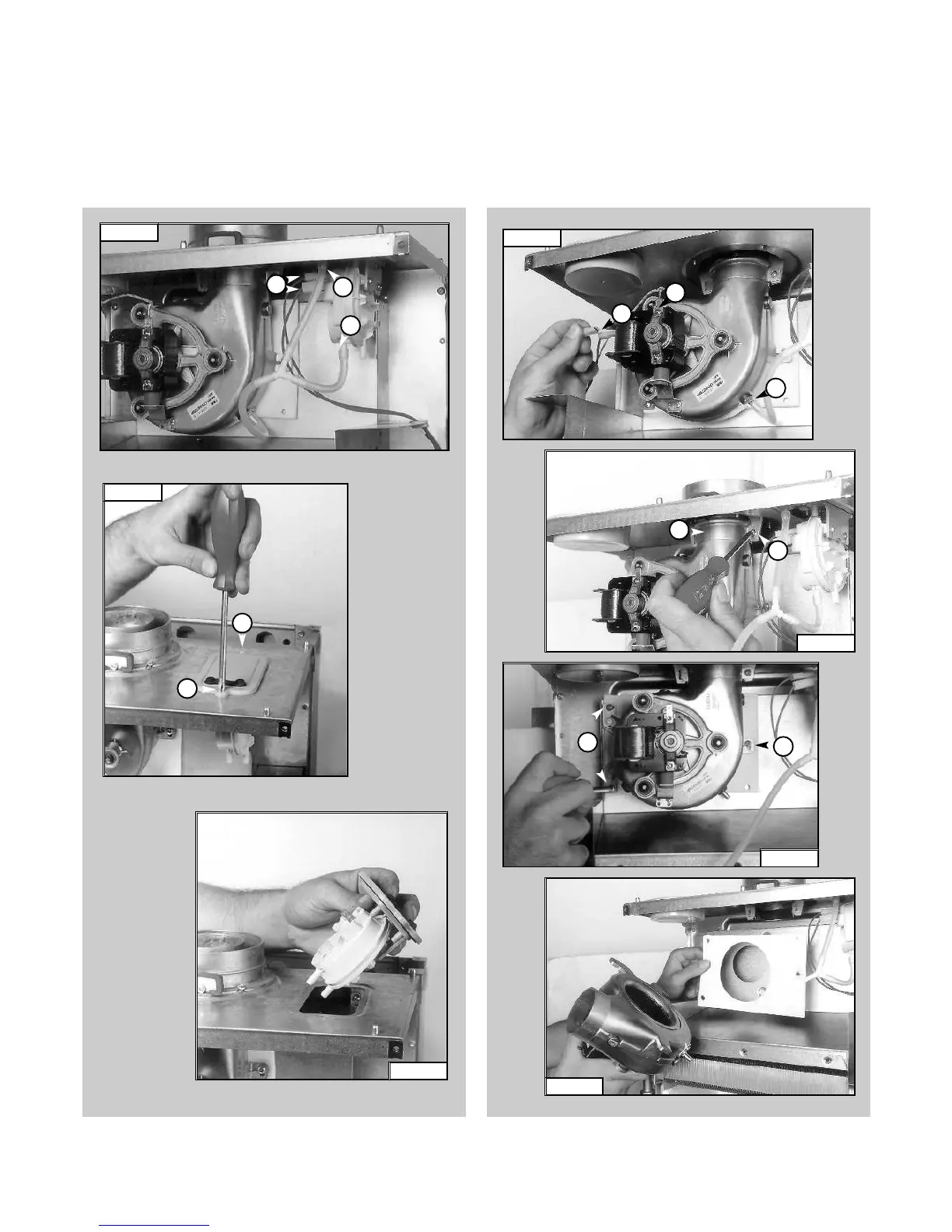
1. Disconnect electrical connections “N” and silicone pipe “O”
(FIG.1.23);
2. Remove screw “P” and remove the fan collar clamp “Q”
(FIG.1.24);
3. Remove screws “R” (FIG.1.25);
4. Remove fan and mounting plate (FIG.1.26).
1.3.6 Removing the fan
1. Disconnect the electrical connections “K” and silicone
pipes “L” from their connection points (FIG. 1.20);
2. Remove screws “M” on the top of the sealed chamber
(FIG. 1.21);
3. Lift out the air pressure switch (FIG. 1.22);
4. Unscrew to remove the switch from the plate.
7
1.3.5 Removing the air pressure switch
FIG. 1.25
R
R
FIG. 1.24
P
Q
FIG. 1.23
N
N
O
FIG. 1.26
FIG. 1.21
FIG. 1.20
L
L
K
M
M
FIG. 1.22

 Loading...