26
M
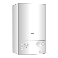
aking the Electrical Connections
Lower the electrical box to gain access to the elec-
t
rical connections. Push in the tabs
P (
Fig. 28) on
either side of the boiler and pivot the box forward.
R
emove the PCB cover (see Section 18.4 - page
51). Connect the live neutral and earth wires to
the main cable.
R
oom thermostats or other external control, they
can be connected in place of the link on the termi-
n
al block (Diagram A - Fig. 30).
N
ote: Use only controls designed for voltage free
switching or 24V supply. Do not connect to a 230V
supply, and do not run 230v cables alongside the
low voltage cables.
A
ll necessary settings for room thermostat opera-
tions are described in Section 17 ADJUSTMENTS
AND SETTINGS.
P
P
Fig. 28
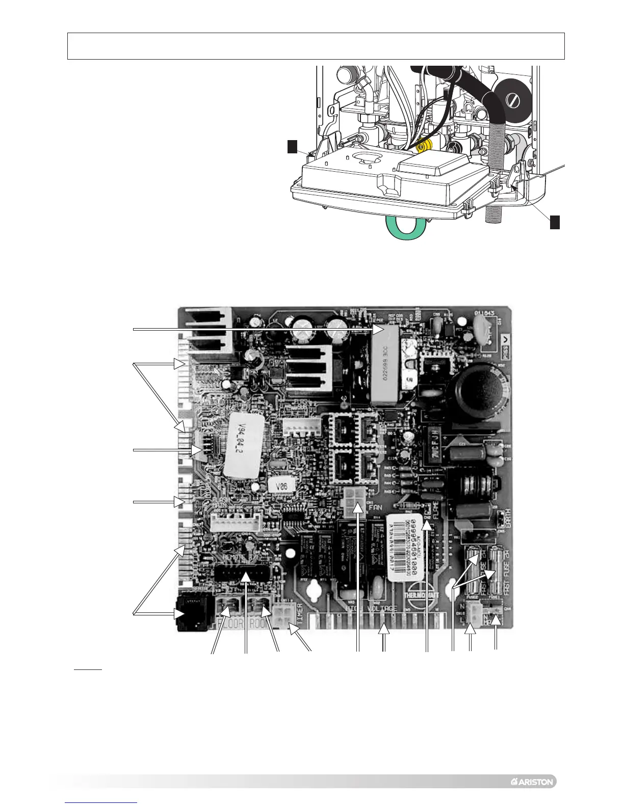
13. Electrical connections
Fig. 29
LEGEND
1 NTC
Connectors
2 Display Connectors
3 EEPROM
Key
4 24V
DC
Supply
5 Fan Connector
6 Flame Detection Connector
7 Fuses 2A
230V (X2)
8 230V
Connector
9 Auxiliary 230V Connector
10 Actuators 230V
Connector
11 Time Clock Connector (Internal)
12 Room Thermostat Connector
13 Remote Control
Connector
14 Under Floor Heating Connector
15 Not Used
1
5
11
12
13
14
15
2
3
4
8
97
6
10