52
18.4.2 Removing the fuses
1. Carry out step 18.4.1;
2. Remove the fuses “X” (see Fig. 105)
3. Reassemble in reverse order.
NOTE:FUSE RATING = 2AMP FAST FUSE
Fig. 105
Fig. 104
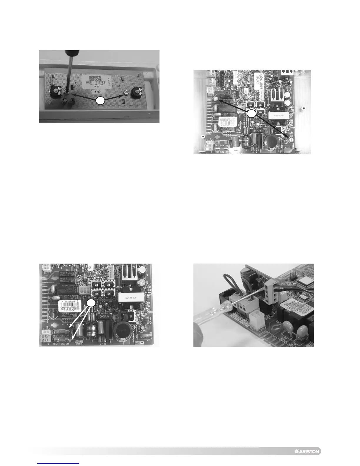
W5
X
Fig. 103
8. To remove the main PCB disconnect all electrical
connections and remove the two screws W5 (see Fig.
104
);
Fit the correct EEPROM supplied with the replacement
PCB;
9. Reassemble in reverse order.
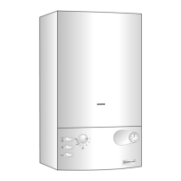
6. To remove the display PCB, remove the two screw
W4 and lift the PCB out (see Fig. 103);
7. Reassemble in reverse order;
W4
18.5 Connecting the external sensor
Fig. 106
1. Access the main PCB as in step 18.4.1;
2. Install the interface PCB supplied in the external
sensot kit on the main PCB
(see Fig. 106);
3. Connect the wires between the external sensor
and the interface PCB* (see Fig. 106).
* ENSURE THAT THE WIRES FOR THE EXTERNAL SENSOR
ARE CONNECTED TO THE TERMINALS INDICATED IN
FIG.
110.
N
OTE:
T
HE
WIRES ARE NOT POLARITY SENSITIVE
.
I
MPORTANT!!
DO NOT FIT THE EXTERNAL SENSOR IN THE EVENT THAT
THE BOILER IS BEING USED TO HEAT AN INDIRECT HOT
WATER
STORAGE
CYLINDER
.