5
USER INSTRUCTIONS
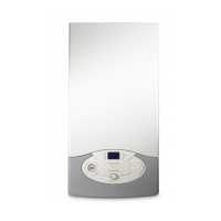
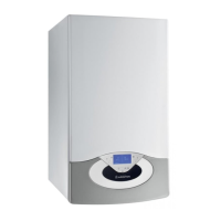
1. Control Panel
30
26
27
25
34
28
Fig. 1
33
31
32
29
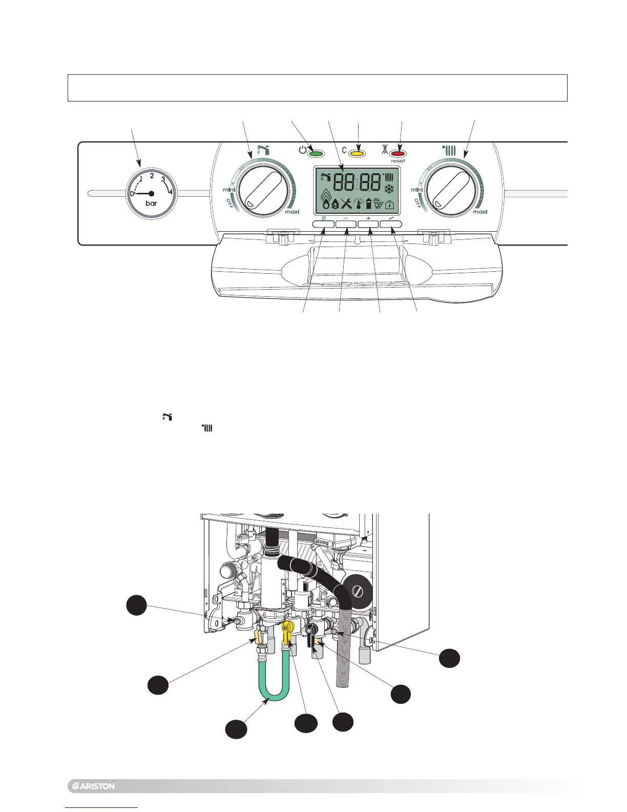
Control panel (Fig. 1)
16.- Pressure gauge
25.- Display
26.- On/off push button and power on indicator light
27.- Yellow indicator - Comfort button
28.- Reset push button and red indicator lock-out light
29.- DHW control knob and temperature setting
30.- Central Heating control knob and temperature setting
31.- Menu button
32.- Reducing button
33.- Increasing button
34.- Setting button
Connecting bracket
Taps shown in Open position (Fig. 2)
39.- Gas Service Tap
40.- Water Service Tap
41.- Central Heating Flow Isolating Valve
42.- Central Heating Return Isolating Valve
43 & 44.- Filling Taps
45.- Filling Loop
Fig. 2
41
42
43
44
45
39
40
16