6 / 18 P/N 466-5570 (EN) • REV E • ISS 22MAR22
any other indirect, special, incidental, or consequential
damages under any theory of liability, whether based in
contract, tort, negligence, product liability, or otherwise.
Because some jurisdictions do not allow the exclusion or
limitation of liability for consequential or incidental damages the
preceding limitation may not apply to you. In any event the total
liability of Carrier shall not exceed the purchase price of the
product. The foregoing limitation will apply to the maximum
extent permitted by applicable law, regardless of whether
Carrier has been advised of the possibility of such damages
and regardless of whether any remedy fails of its essential
purpose.
Installation in accordance with this manual, applicable codes,
and the instructions of the authority having jurisdiction is
mandatory.
While every precaution has been taken during the preparation
of this manual to ensure the accuracy of its contents, Carrier
assumes no responsibility for errors or omissions.
Warnings and cautions
Caution: Hot parts! Risk of burn. Burned fingers
when handling parts. Allow parts to cool down
before handling.
WARNING! Dangerous voltage! Risk of injury or
death. Fuse may be in the neutral. The mains
should be disconnected to de-energize the
phase conductors.
WARNING! Risk of fire, explosion, or safeguard
malfunction if the battery is replaced by an
incorrect type. Disposal into fire, placing into a
hot oven, leaving in an extremely high
temperature surrounding environment,
subjecting to extremely low air pressure,
mechanically crushing or cutting of a battery can
result in an explosion or leakage of flammable
liquid or gas.
WARNING! If the housing cover is removed,
there is no safeguard against electrically caused
fire that might occur during system malfunction.
The housing cover must be reassembled
according to this installation instruction after
each interference by a user.
General installation information
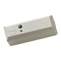
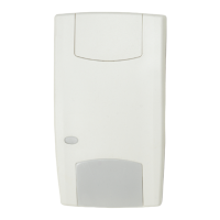
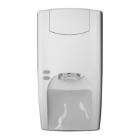
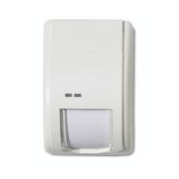
Advisor Advanced housings
The housings with mounting holes (items 1) are shown in
figures below.
Item 2 indicates the pry-off tamper wall stub location.
All dimensions are given in mm.
For more details on connections and connecting devices to the
Advisor Advanced, see “Cabling” on page 8.
For details on connecting pry-off tampers, see “Pry-off tamper
mounting” below.
Pry-off tamper mounting
For medium (MM and MM+), and large housings (LM), follow
the steps in Figure 6. For large plastic housing (LP), follow the
steps in Figure 7.
Caution: Once the ATS-MM-TK tamper assembly has been
fitted, the wires coming from the tamper microswitch must be
wrapped around and secured to one of the nearby fixing pillars,
so that there is no slack left in the tamper wiring between the
microswitch and the pillar it is wrapped around.
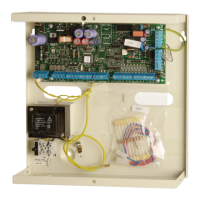
Advisor Advanced layout
Figure 8: Advisor Advanced ATSx500A(-IP) PCB layout
(1) Interface to output expander
(2) USB fault LED
(3) USB power LED
(4) USB connector (micro-A/B type)
(5) Ethernet RJ-45 connector (ATS-IP only)
(6) IP communication LED (ATS-IP only)
(7) Heartbeat LED
(8) MI-bus connector for MI devices
(9) Interface to input expander
(10) Interface to PSTN module
(11) Optional: enclosure ambient temperature sensor
(12) ATS670 databus expander connector
(13) Panel earth terminal
(14) External tamper switch
(15) RS-485 system databus connections
(16) T2: Device firmware upgrade mode (DFU)
(17) RS-485 system databus communication LEDs
(18) T1: Restores installer default PIN
(19) System databus termination jumper
(20) AC power supply terminal
(21) Battery connection
(22) Low current (OC) outputs
(23) High current outputs
(24) Siren tamper switch
(25) 12 VDC auxiliary power output
(26) Zone inputs
The intrusion control panel is only allowed to be serviced by
dedicated service personal. The screw of the housing is
intended to protect the product from unintended use.
For metal housing, the screw is already installed out of the box.
For plastic housing, the screw, available inside housing, should
be mounted before first time use.
To open the housing, remove the housing screw and open the
cover.
After the maintenance, replace the cover and fix it with the
cover screw.
Electrical installation should be carried out by a skilled person.
Solid insulation of the building mains cables should meet the
technical and the environmental specifications of the
equipment.
Wire insulation of cables connected to the equipment must
conform to IEC 60332-1-2 and IEC 60332-1-3 or IEC 60332-2-
 Loading...