EN: Installation Instructions
Description
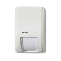
The EV660 series includes models EV666-D with Form C
relay, and EV669 with Form A relay. These are ceiling mount
PIR detectors with 360° coverage.
Mounting the detector
Install the detector so that the expected movement of an
intruder will be across the fields of view. This is the direction
best detected by PIR detectors. See Figure 7.
Avoid possible false alarm sources such as:
• Direct sunlight onto the detector
• Heat or cold sources in a field of view (heaters, air
conditioning, radiators, etc.)
• Moving objects in the field of view (fans, pets, etc.)
• Obscuring the detector field of view with large objects,
such as furniture
Increase of mounting heights beyond the specified (2.5 to
5.0 m) range will reduce sensitivity.
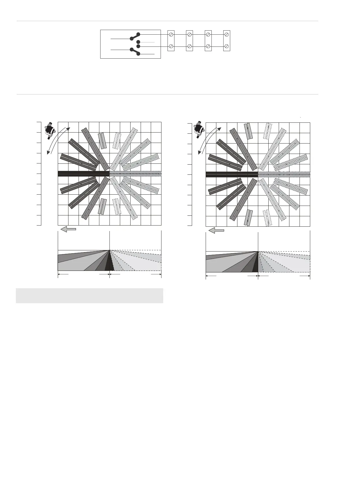
Note: The arrow (Figure 2, item 4, and Figure 7) indicates the
centre curtain direction and the active direction when switch 4
is set to ON.
Mounting instructions
See Figure 2.
1. Lift off mounting plate (item 1) as shown.
2. Fasten the mounting plate to the ceiling in the required
position using mounting holes (item 3).
3. Ensure the mounting height is 2.5 to 5.0 m.
4. The detection pattern can be adjusted by up to ±15°
(max 30°) by rotation of the mounting plate prior to
tightening the screws.
5. Strip cable for 5 cm and pull it through the cable entry hole
(item 5) and strain relief.
6. Wire the detector and select the appropriate processing
options (see “DIP switch settings” on page 3) and mount
the sensor module (item 8).
1
1
2
3
4
5
6
7
8
9
9
8
7
6
5
4
3
2
Shaded area is shunted
when switch 4 is in
position
“ON”
Floor pattern at mounting heights above
3.0 m (9 10 ) ft. in.
10 m
(32 ft. 10 in.)
8 m
(26 ft. 3 in.)
6 m
(19 ft. 8 in.)
4 m
(13 ft. 2 in.)
2 m
(6 ft. 7 in.)
0 m
2 m
(6 ft. 7 in.)
4 m
(13 ft. 2 in.)
6 m
(19 ft. 8 in.)
8 m
(26 ft. 3 in.)
10 m
(32 ft. 10 in.)
> 3 m
(> 9 ft. 10 in.)
10 m (32 ft. 10 in.) 10 m (32 ft. 10 in.)
0 m
1
1
2
3
4
5
6
7
8
9
9
8
7
6
4
3
2
Shaded area is shunted
when switch 4 is in
position
“ON”
Floor pattern at mounting heights between
2.5 and 3.0 m (8 2 and 9 10 ) ft. in. ft. in.
10 m
(32 ft. 10 in.)
8 m
(26 ft. 3 in.)
6 m
(19 ft. 8 in.)
4 m
(13 ft. 2 in.)
2 m
(6 ft. 7 in.)
0 m
2 m
(6 ft. 7 in.)
4 m
(13 ft. 2 in.)
6 m
(19 ft. 8 in.)
8 m
(26 ft. 3 in.)
10 m
(32 ft. 10 in.)
2.5 3 m-
(8 ft. 2 in. - 9 ft. 10 in.)
10 m (32 ft. 10 in.) 10 m (32 ft. 10 in.)
0 m
An arrow inside the
mounting plate and sensor
module indicates the
always active direction
An arrow inside the
mounting plate and sensor
module indicates the
always active direction