1
2
3
4
5
PELLET BOILER UNO
ARITERM SWEDEN AB Installation Instructions - 2008.05.21 - 15/28
Burner settings
First start
The burner is not factory adjusted. It must be adjusted at the first start. The burner
should normally be used with two output positions; high and low, but the low out-
put position can be disabled by an easy adjustment on the circuit board. If the flue
gas temperature is too low, the burner should only be operating in the high output
position to avoid condensation problems in the chimney.
Exception: If the chimney is provided with an insert tube, some condensation can be
accepted; ask your chimney sweep for advice.
To set air and fuel quantities
1. Fill the feeder screw with pellets before connecting it to the burner. Connect
the burner cable to the feeder screw motor. Let the motor run a few minutes
after the feeder screw has been filled to ensure that it is completely full.
2. Set the starting dose (pellet quantity for ignition) by pot 2, turn clockwise to
increase the quantity. 0.3 to 0.4 litres is a moderate dose.
A change of the starting dose will not be activated until next start.
3. To set the fuel quantity (output) for operation:
Start the burner, wait 5 minutes after the start of the operational phase (green
diode shows fixed beam), adjust pot 1 to the correct flue gas temperature.
The screw conveyor normally makes less than half a revolution during each
feedingcycle(KMPstandardscrew).
Air settings
For optimal setting, a flue gas gauge should be used (ask your installation technician).
Correct setting of the air quantity is important for economic combustion.
Greyorblackchimneysmokeindicatestoolittleair.Whitesmokemostlyconsistsof
steam, which is normal during certain weather conditions.
To set low output position
Wait until the burner is in the low output position (yellow light), set the air quantity
by pot 4 in the same way as setting the high output position. The output (the feed-
ing) will automatically be 80 % of the high output position.
To switch off the low output position
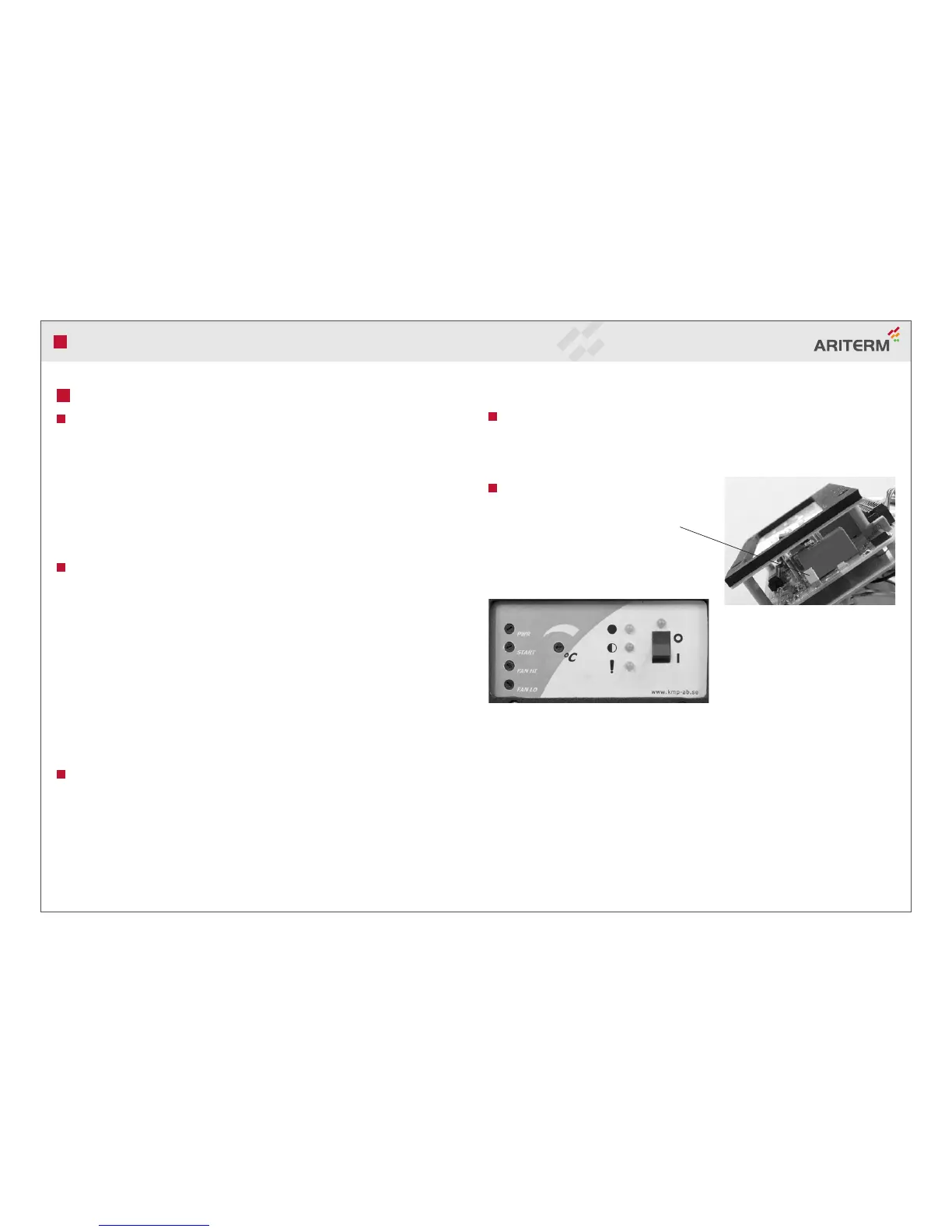
Remove the bracket on the right-hand side
of the circit board.
Fig 4.
Potentiometers for adjustment.
Pot 1: Fuel quantity, opertional phase.
Pot 2: Fuel quantity, starting dose.
Pot 3: Air quantity, high output position.
Pot 4: Air quantity, low output position
Pot 5: Boiler temperature
Fig 3.
Bridge for high and low output.


 To Next Page