507405-05Page 36 of 72 Issue 1621
Electrical
ELECTROSTATIC DISCHARGE (ESD)
Precautions and Procedures
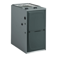
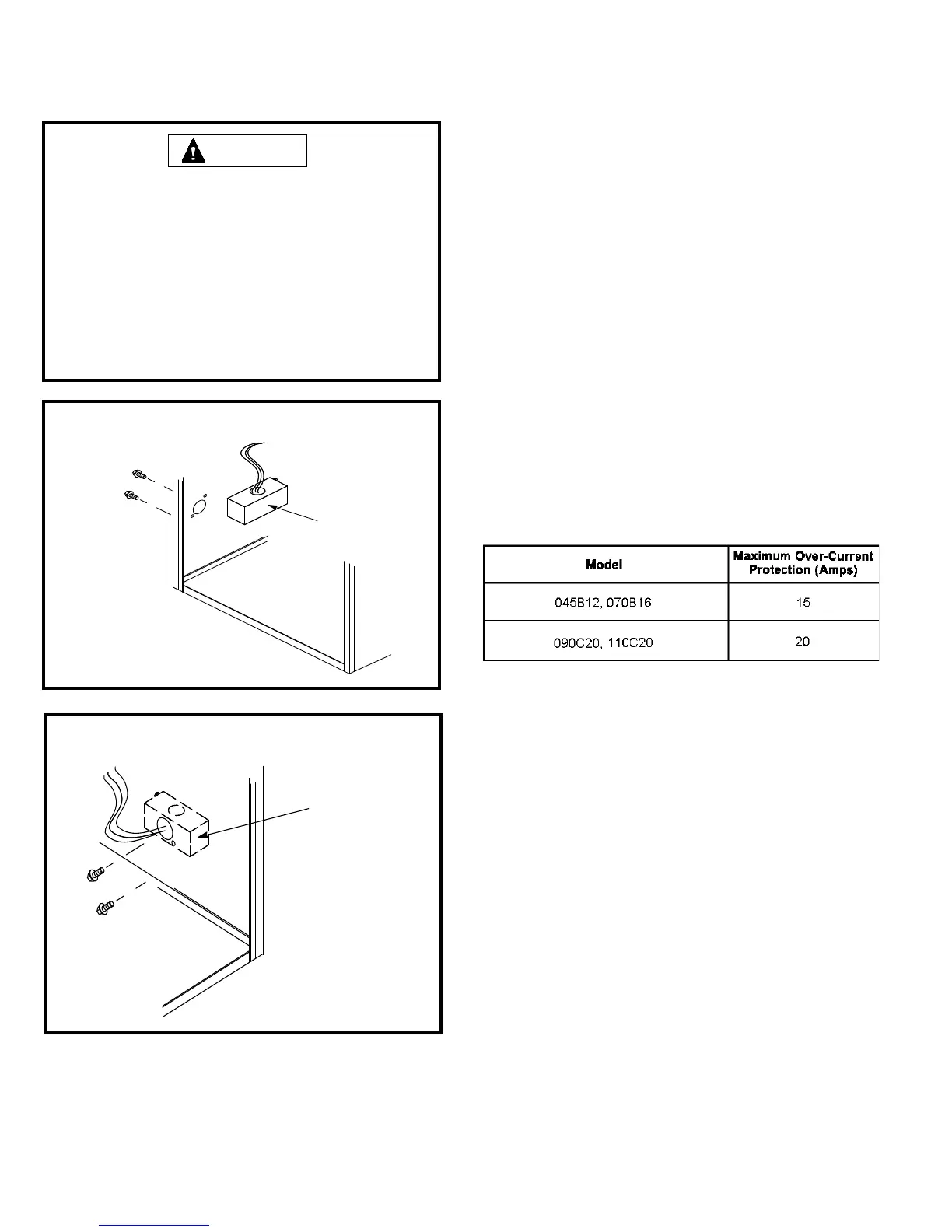
The unit is equipped with a eld makeup box. The makeup
box may be installed on the exterior of the right side of the
furnace to facilitate installation. Seal unused openings
on left side with plugs removed from right side. Secure
the excess wire to the existing harness to protect it from
damage.
1) Refer to gures 53 and 54 for eld wiring when using
the Comfort Sync thermostat. Refer to tables 12A, 12B,
12C, and 12D for eld wiring for all non-communicating
applications.
1. The power supply wiring must meet Class I restrictions.
Protected by either a fuse or circuit breaker, select circuit
protection and wire size according to unit nameplate.
NOTE: Unit nameplate states maximum current draw.
Maximum over current protection allowed is shown in Table
11.
2. Holes are on both sides of the furnace cabinet to
facilitate wiring.
3. Install a separate (properly sized) disconnect switch
near the furnace so that power can be turned off for
servicing.
4. Before connecting the thermostat, check to make sure
the wires will be long enough for servicing at a later
date. Make sure that thermostat wire is long enough
to facilitate future removal of blower for service.
5. Complete the wiring connections to the equipment. Use
the provided unit wiring diagram and the eld wiring
diagram. Use 18 gauge wire or larger that is suitable
for Class II rating for thermostat connections.
6. Electrically ground the unit according to local codes or,
in the absence of local codes, according to the current
National Electric Code (ANSI/NFPA No. 70). A green
ground wire is provided in the eld make-up box.
NOTE: This furnace contains electronic components that
are polarity sensitive. Make sure that the furnace is wired
correctly and is properly grounded.
7. One line voltage “EAC” 1/4” spade terminal is provided
on the furnace integrated control. Any electronic air
cleaner or other accessory rated up to one amp can
be connected to this terminal with the neutral leg of the
circuit being connected to one of the provided neutral
terminals. This terminal is energized when the indoor
blower is operating.
Table 11
Electrostatic discharge can affect electronic components.
Take precautions during furnace installation and service
to protect the furnace’s electronic controls. Precautions
will help to avoid control exposure to electrostatic
discharge by putting the furnace, the control and the
technician at the same electrostatic potential. Neutralize
electrostatic charge by touching hand and all tools on
an unpainted unit surface, such as the gas valve or
blower deck, before performing any service procedure.
CAUTION
Figure 51
INTERIOR MAKE-UP BOX INSTALLATION
MAKE−UP
BOX INSIDE
CABINET
Left side
Figure 52
INTERIOR MAKE-UP BOX INSTALLATION
MAKE−UP
BOX
OUTSIDE
CABINET
Right Side