507405-05 Page 53 of 72Issue 1621
9. Replace the heating compartment access panel.
10. Turn on all electrical power to the unit.
11. Set the thermostat to desired setting.
NOTE: When unit is initially started, steps 1 through 11 may
need to be repeated to purge air from gas line.
12. If the appliance will not operate, follow the instructions
“Turning Off Gas to Unit” and call your service technician
or gas supplier.
Turning Off Gas to Unit
1. Set the thermostat to the lowest setting.
2. Turn off all electrical power to the unit if service is to be
performed.
3. Remove the heating compartment access panel.
4. Move gas valve switch to OFF.
5. Replace the heating compartment access panel.
Gas Pressure Adjustment
Gas Flow (Approximate)
Furnace should operate at least 5 minutes before checking
gas ow. Determine time in seconds for two revolutions of
gas through the meter. (Two revolutions assures a more
accurate time.) Divide by two and compare to time in
Table 14. If manifold pressure matches Table 15 and rate
is incorrect, check gas orices for proper size and restriction.
Remove temporary gas meter if installed.
NOTE: To obtain accurate reading, shut off all other gas
appliances connected to meter.
Supply Pressure Measurement
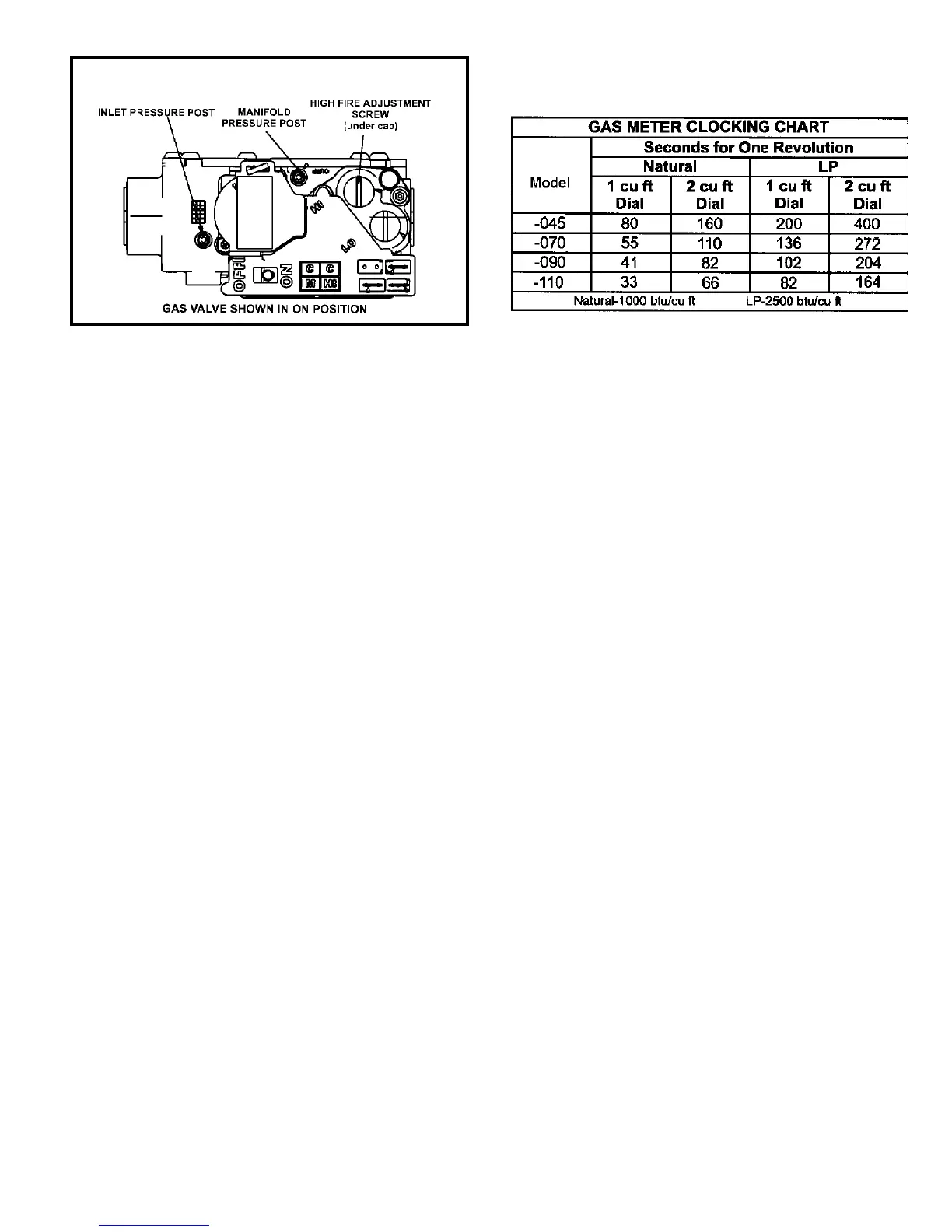
A pressure post on the inlet side of the gas valve
provides access to the supply pressure. Back out the
3/32 Hex screw one turn, connect a piece of 5/16”
tubing and connect a manometer to measure supply
pressure.
NOTE: Shut unit off and remove manometer as soon as an
accurate reading has been obtained. Take care to re-tighten
the 3/32 Hex screw.
Manifold Pressure Measurement
1. A manifold post located on the gas valve provides
access to the manifold pressure. See Figure 57. Back
out the 3/32 Hex screw one turn, connect a piece of
5/16” tubing and connect to a manometer to measure
manifold pressure.
2. Start unit and allow 5 minutes for unit to reach steady
state.
3. While waiting for the unit to stabilize, observe the ame.
Flame should be stable and should not lift from burner.
Natural gas should burn blue.
4. After allowing unit to stabilize for 5 minutes, record
manifold pressure and compare to value given in Table
15.
NOTE: Shut unit off and remove manometer as soon as an
accurate reading has been obtained. Take care to re-tighten
the 3/32 Hex screw.
Table 20
Figure 57
Gas Valve Shown In “ON’ Position