installation &
operating instructions
Design Envelope 4300 & 4380 Vertical
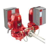
In-line pumping unit with ivs drive
6
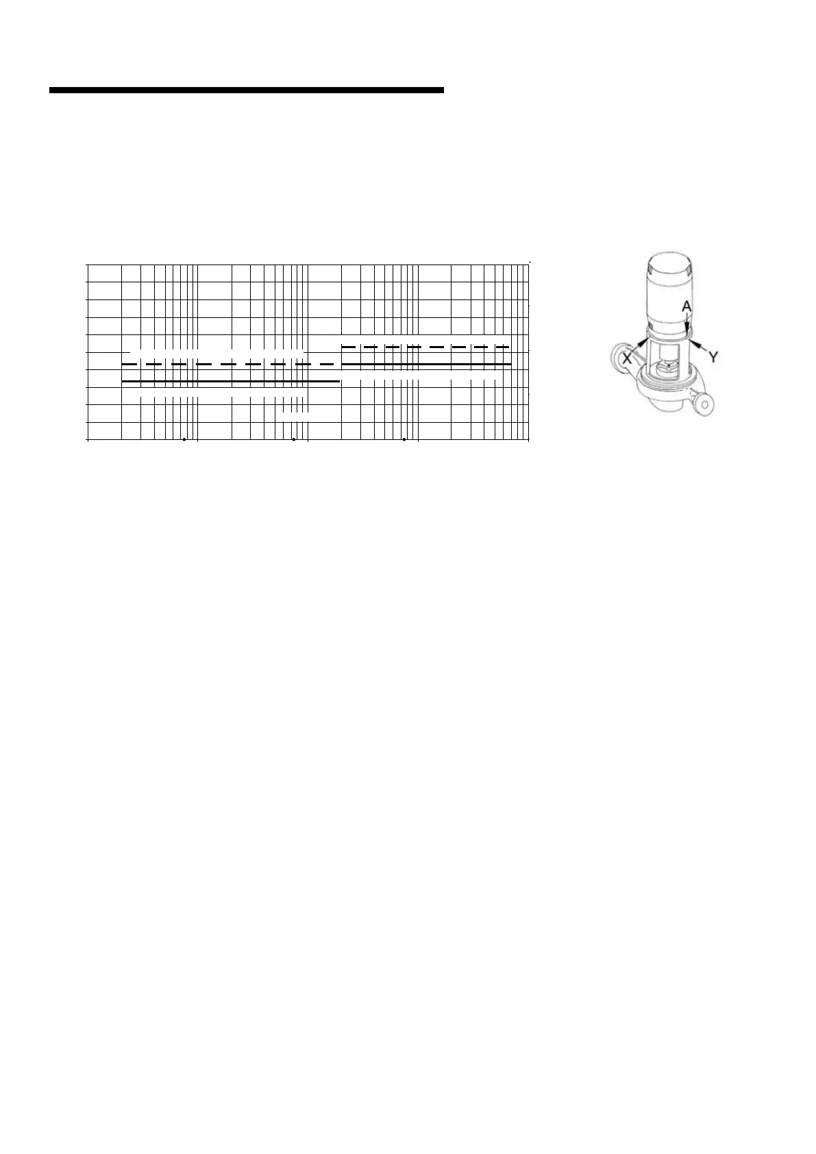
1.1.5 vibration levels
Armstrong Vertical In-Line pumps are designed to meet
vibration levels set by Hydraulic Institute Standard hi Pump
Vibration 9.6.4. Standard levels are as detailed below:
1.1.6 storage
Pumps not immediately placed into service, or removed from
service and stored, must be properly prepared to prevent
excessive rusting. Pump port protection plates must not be
removed until the pump is ready to connect to the piping.
Rotate the shaft periodically (at least monthly) to keep rotat-
ing element free and bearings fully functional.
For long term storage (longer than three months), the pump
must be placed in a vertical position in a dry environment.
Internal rusting can be prevented by removing the plugs at
the top and bottom of the casing and drain or air blow out all
water to prevent rust buildup or the possibility of freezing. Be
sure to reinstall the plugs when the unit is made operational.
Rustproofing or packing the casing with moisture absorb-
ing material and covering the flanges is acceptable. When
returning to service be sure to remove the drying agent from
the pump.
1.1.7 warranty
Armstrong’s warranty period for Design Envelope pumps
is [18] months from date of shipment, or [12] months from
date of installation, whichever comes first. Please refer to File
9.10uk / 9.10in for full terms and conditions. To receive
an additional [6] months of standard coverage, owner may
register the pump unit at
www.armstrongfluidtechnology.com/warrantyregistration
1.1.8 uncrating
Armstrong Vertical In-Line pumps are thoroughly inspected
before shipment to assure they meet with your order require-
ments. After removing the pump from the packaging, make
sure the equipment is in good order and that all components
are received as called for on the packing list. Any shortages or
damage should be reported immediately.
1.1.8.1 de ivs units
Use extreme care in handling the unit, placing slings and
hooks carefully so that stress will not be imposed on the
integrated controls, pump or motor. Never place cable slings
around the pump shaft or integrated controls. The eye bolts
or lifting lugs on the motor are intended for lifting only the
motor and not the complete unit.
1.1.8.2 depm ivs units
Use extreme care in handling the unit, placing slings and
hooks carefully using the eye bolts. Never place cable slings
around the pump shaft or integrated controls The eye bolts
or lifting lugs on top of motor are intended for lifting the
complete unit.
1.1.9 handling design envelope 4300 & 4380
units
1.1.9.1 de ivs units
To handle Design Envelope 4300 and 4380 units from
shipment, secure the pallet following uncovering the unit, then
placestraps behind the integrated controls (around the motor
feet) and carefully lift the pumping unit to stand the pump
vertically upright. Lift only suciently to remove the pallet,
then lower onto a flat surface. The pump and motor unit will
free-stand on the casing ribs.Extra care is required to ensure
the integrated controls do not get damaged during lifting and
installation.
Factory 5.3 mm/s (0.21 in/s) 200 kW (268 bhp) & above
Factory 4.3 mm/s (0.17 in/s) below 200 kW (268 bhp)
Field 3.3 mm/s (0.13 in/s) below 200 kW (268 bhp)
Overall Vibration Velocity (mm/s) RMS
Overall Vibration Velocity (in/s) RMS
Pump power, bhp
Pump power, kW
Field 4.3 mm/s (0.17 in/s) 200 kW (268 bhp) & above
10
101
0
1
2
3
4
5
6
7
8
9
10
100
100
1000
1000 10000
0
0.1
0.2
0.3
0.4


 To Next Page