installation &
operating instructions
Design Envelope 4300 & 4380 Vertical
In-line pumping unit with ivs drive
7
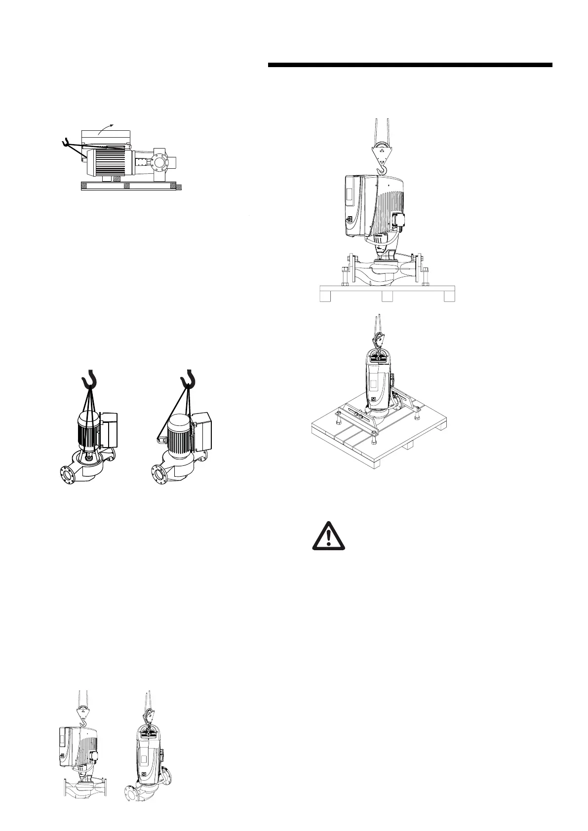
For Design Envelope 4300 units, remove the coupling guard
and insert lifting straps through the pump/motor pedestal on
either side of the coupling. For Design Envelope 4380 units,
remove the motor eye-bolt and install a swivel hoist ring tied
to a lifting strap. Place secondary lifting straps around the
motor feet (and/or spacers). As the lifting device is engaged
(Using a spacer bar if necessary) and the straps tighten
ensure no part of the strapping is touching any part of the
control or motor fan cover. Lift the pumping unit carefully
from the pallet in this manner and allow the unit to stand
upright on a flat surface and re-position the straps, if
necessary, to ensure safe and damage-free transportation
into the pipe installation.
4300
4380
Remove coupling guard and
place lifting straps on each side
of coupling, use spacer bar if nec-
essary to protect the integrated
controls and motor fan cover.
Remove the motor eye-bolt and
install a swivel hoist ring tied to a
lifting strap. Place secondary lift-
ing straps securely around motor
feet (and/or spacers).
1.1.9.2 depm ivs unit
depm ivs Vertical Inline units are shipped upright, secured to
a pallet. Once the protective box covering is removed, install
a pulley to the overhead lifting eye bolt. Remove the bolts
from the stand supports so that the pump is not secured to
the bottom pallet. Lift suciently to remove from the pallet,
then lower onto a flat surface. The stand supports should stay
on the pump ports until ready for installation to piping. The
vertical inline pumps will not free-stand without the stand
supports.
important:
Do not run the pump for any length of time under
very low flow conditions or with the discharge valve
closed. To do so could cause the water in the casing
to reach super heated steam conditions and will cause
premature failure and could cause serious and dramatic
damage to the pump and surrounding area.
1.2 mechanical installation
1.2.1 location
In open systems, locate the unit as close as practical to the
liquid being pumped, with a short, direct suction pipe. Ensure
adequate space is left above and around the unit for opera-
tion, maintenance, service and inspection of parts.
In closed systems, where possible, the pumps should be
installed immediately downstream of the expansion tank /
make-up connection. This is the point of zero pressure change
and is necessary for eective pump operation. Do not install
more than one expansion tank connection into any closed
hydronic system.
 Loading...