12
Armstrong International
221 Armstrong Blvd., Three Rivers, Michigan, 49093 - USA
Ph. (269) 279-3602 Toll Free (888) 468-4673 Fax (269) 279-3130
H C
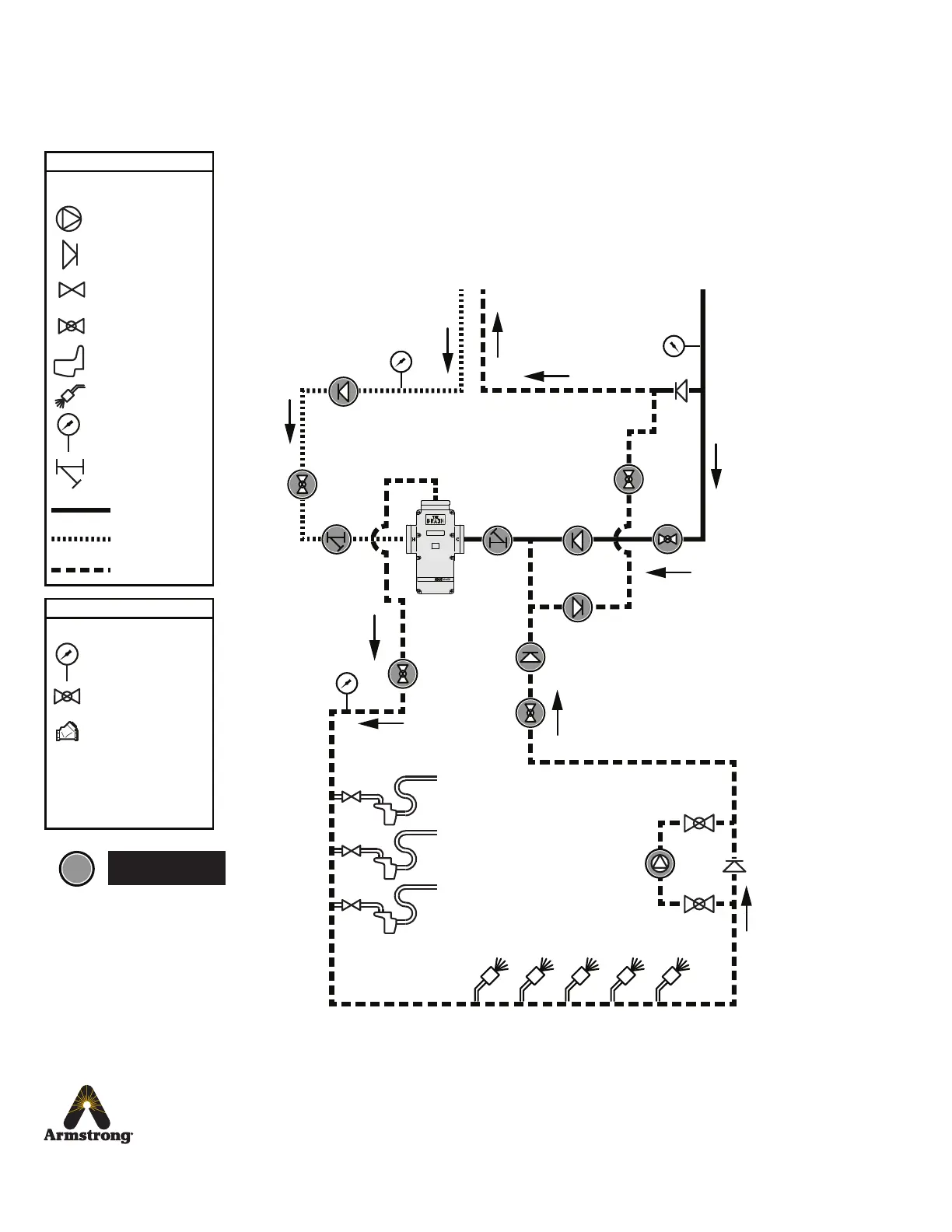
Isolation Valve
Sink
Shower
Thermometer
Strainer
Cold Water
Hot Water
Mixed Water
Check Valve
Recirculation Pump
System Layout
- Legend -
Stop Valve
DRV80 Assembly
Swing Check Valve*
- Legend -
Thermometer
Isolation Valve
*Orientated for piping
schematic detail only.
Must be installed in
horizontal plane.
Outlets
Return to
Hot Water
Supply Inlet
Cold Water
Supply
Mixed Return
From Hot Water
Supply
Items are installer
supplied
Outlets
DRV
Figure 12-1. Single Valve Installation
Note: For 0-90 GPM Systems the DRV80 inlet connections are 2”
Note: For 0-150 GPM Systems the DRV80 inlet connections are 3”
Mixed Flow
Piping Diagrams
 Loading...