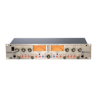
Do you have a question about the Art DIGITAL MPA and is the answer not in the manual?
| frequency response at normal plate voltage | 15Hz to 48 kHz (+0, -1dB) |
|---|---|
| frequency response at high plate voltage | 15Hz to 120 kHz (+0, -1dB) |
| A/D frequency response at 44.1KHz sample rate | 10Hz to 21.25KHz (+0, -1dB) |
| A/D frequency response at 88.2KHz sample rate | 10Hz to 42.50KHz (+0, -1dB) |
| A/D frequency response at 196KHz sample rate | 10Hz to 81KHz (+0, -1dB) |
| dynamic range | >110dB (“A” weighted) |
|---|---|
| A/D dynamic range | >115dB “A” weighted (typ.) |
| maximum gain | 75dB |
| THD | <0.005% (typical) |
|---|---|
| A/D THD | <0.001% @1K (typ.) |
| equivalent input noise | -133dBu (XLR, “A” weighted) |
| maximum input level | +20dBu (cannon) |
|---|---|
| maximum instrument input | +17dBu |
| maximum output level | +27dBu (XLR) |
| input impedance | 150-3000 Ohms adjustable (XLR) >800K Ohms (Instrument) |
|---|---|
| output impedance | < 47 Ohms (XLR) |
| A/D insert input impedance | >10K Ohms |
| power requirements | 100-125 VAC, 25W |
|---|---|
| high pass filter | single pole, 10-200 Hz adjustable |
| meter calibration | 0 VU = +4dBu output |
| dimensions | 6.5” D x 19.0” W x 3.5” H |
|---|---|
| weight | 12 Lb. |
Control for input signal level before tube gain, adjustable from 0dB to 45dB.
Controls Mic/line input amplifier impedance for variable microphone voicing.
Adjusts output signal level at rear output jacks, from +10dB gain to mute.
Single tuned High Pass Filter to remove low frequencies, adjustable from 10 Hz to 200 Hz.
Provides an additional 20dB gain and drives the tube harder for more character.
Turns phantom power (48V) on/off for condenser microphones and other devices.
Inverts the phase of the audio signal path in either channel for phase alignment.
Sets tube bias point and plate voltage, affecting headroom and tube saturation characteristics.
Allows analog meters to monitor output signal or tube output level.
Adjusts levels driving the A/D converter, variable from +10dB to -∞.
Adds dither component to improve sound quality when truncating 24-bit to 16-bit data.
Determines output sample rate and digital data format (AES/EBU or S/PDIF).
Selects digital output format for the optical jack (ADAT or S/PDIF).
1/4" jacks on the front panel for instrument input, with high impedance (>1M Ohm).
XLR connectors for balanced inputs, with variable impedance (150-3000 Ohms).
Active balanced outputs on 1/4" and XLR connectors, offering low impedance.
Jacks for audio processing before A/D conversion, wired Tip=Input, Ring=Output.
BNC connectors for Wordclock input, accepting 5V logic level signals for timing.
Optical connector for ADAT timing sync and data source for channels 3-8.
Selects data source for the optical jack, outputting ADAT or S/PDIF.
Coax connector for consumer/pro equipment, 75 Ohm impedance.
Cannon connector with 5V p-p signal and 110 Ohm impedance.
Procedure for setting input gain and levels for optimal noise performance and dynamic range.
Fine-tuning microphone voicing by adjusting the input impedance for desired interaction.
Guide for setting digital level control and input gain for optimal A/D conversion and headroom.
Selecting between "Warm" and "High" plate voltage settings for different tube characteristics.
Outlines the five-year warranty, coverage, and terms for product defects.
Details conditions under which the warranty is void, such as misuse or alterations.
Instructions for troubleshooting, contacting support, and returning the unit for repair.
 Loading...